Siemens – Siemens launches world’s first heavy duty direct current contactor for up to 1500 V
- Innovative hybrid technology combines semiconductors and mechanics
- Wear-free electronic switching of up to 1,500 V and 600 A
- Complements Siemens’ comprehensive direct current portfolio
- Ideal for switching in energy storage, e-mobility charging, PV and marine applications
Siemens is expanding its direct current (DC) portfolio with the world’s first semiconductor-based heavy duty DC contactor for high DC currents up to 600 A and voltages up to 1,500 V. The new SIRIUS 3QC1 contactor enables galvanic isolation, and reliable and wear-free switching of high DC loads through innovative semiconductor technology. The enlarged portfolio allows customers to more quickly adopt DC grids.
DC systems offer significant advantages, including up to 8 percent energy savings by reducing AC-DC conversions and enabling direct renewable energy and battery storage integration. They can also save up to 50 percent on materials due to reduced cross-section of cables and the need for fewer conductors and components.
The heavy duty DC contactor combines the advantages of semiconductors and mechanical contacts: the semiconductors handle the actual switching process precisely and wear-free, preventing any arcing. During operation, the mechanical contacts are closed and ensure low-loss current conduction. This combination leads to exceptional durability of at least 150,000 switching cycles. The mechanical contacts also ensure galvanic isolation for maximum reliable interruption of the conducting path.
“The shift to direct current is a gamechanger for energy efficiency and the integration of renewables. Our new DC contactor is a crucial building block in this transformation, making sustainable power practical and scalable. It’s a prime example of how Siemens’ innovations are accelerating the energy transition and paving the way for a more decarbonized world,” said Markus Grabmeier, President Electrical Products at Siemens AG.
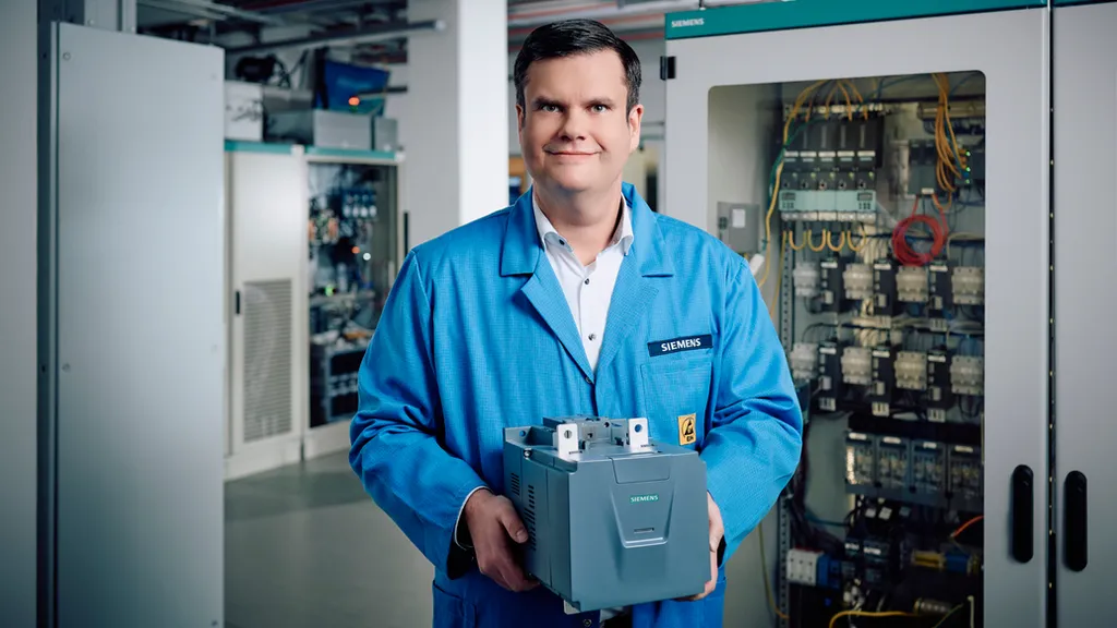
Markus Grabmeier, President Electrical Products at Siemens AG, with the high-performance DC contactor in Siemens’ DC research laboratory in Erlangen, Germany.
A key feature of the SIRIUS 3QC1 is its bidirectionality, which allows it to switch independently of the current’s direction. This makes it the ideal solution for applications involving charging and discharging processes, such as battery energy storage systems (BESS). These BESS facilities can utilize heavy duty DC contactors in standard power racks (100 kW) and high-power racks (up to 375 kW / 300 A at 1,500 V). In e-mobility, they support megawatt fast-charging stations for fleets, e-trucks, and e-buses, with power ratings up to 1,000 kW. The technology is also suitable for marine applications, specifically on ships. Furthermore, it can be used in industrial DC microgrids to couple PV and storage, thereby maximizing independence from AC grid failures.
With the SIRIUS 3QC1 contactor, Siemens offers a simple, cost-effective, compact and familiar design featuring a contactor and a fuse. This solution provides low initial investment costs, and due to the robustness achieved through wear-free switching, the device is durable and maintenance-free, thereby reducing the plant’s maintenance costs. The DC contactor is also remotely switchable, increasing operational convenience and eliminating the need for manual on-site intervention.
The SIRIUS 3QC1 heavy duty DC contactor will be available in several current ratings: 300 A, 400 A, 500 A, and 600 A. It will operate with a control voltage of 24 V DC and can function at extreme temperatures, from -25 °C to +60 °C, with up to 95 percent humidity. Its compact design includes an integrated display with status and condition LEDs.
The new heavy duty DC contactor will be presented to the public for the first time at the Smart Production Solutions (SPS) trade fair held from November 24 to 26, 2026 in Nuremberg, Germany. The Siemens booth will be in Hall 11.
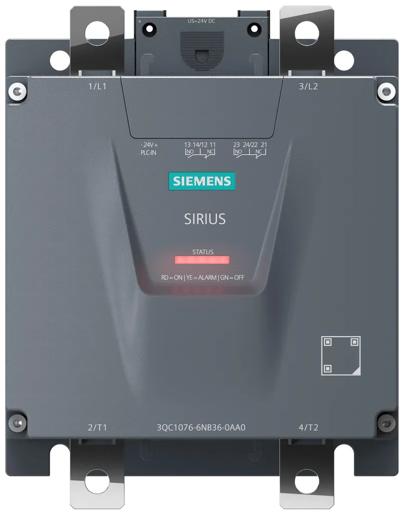
The new SIRIUS 3QC1 heavy duty DC contactor enables galvanic isolation, and reliable and wear-free switching of high DC loads through innovative semiconductor technology.
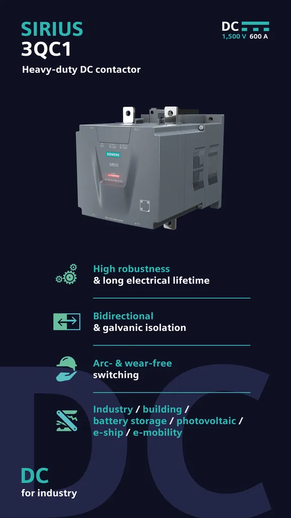
Key features at a glance
SourceSiemens
EMR Analysis
More information on Siemens AG: See full profile on EMR Executive Services
More information on Dr. Roland Busch (President and Chief Executive Officer, Siemens AG): See full profile on EMR Executive Services
More information on Veronika Bienert (Member of the Managing Board and Chief Financial Officer, Siemens AG): See full profile on EMR Executive Services
More information on “ONE Tech Company” Program by Siemens AG: See full profile on EMR Executive Services
More information on Siemens Smart Infrastructure (SI) by Siemens AG: See the full profile on EMR Executive Services
More information on Dr. Peter Körte (Member of the Managing Board and Chief Technology and Chief Strategy Officer with responsibility for Siemens Xcelerator and Siemens Advanta, Siemens AG + Member of the Managing Board and Chief Executive Officer, Siemens Smart Infrastructure (SI), Siemens AG): See the full profile on EMR Executive Services
More information on Markus Grabmeier (Chief Executive Officer, Electrical Products (EP) Business Unit, Siemens Smart Infrastructure (SI), Siemens AG): See the full profile on EMR Executive Services
More information on SIRIUS Industrial Controls by Siemens AG: https://www.siemens.com/en-us/products/sirius/ + Our unique, comprehensive portfolio of SIRIUS products fit every industrial control application. Their modular design makes it simple to plan and build them into a control cabinet and are especially easy to integrate into distributed systems. With the SIRIUS portfolio, you can choose everything you need for:
- Controlling and protecting with SIRIUS Control
- Optimally starting motors with SIRIUS Start
- Commanding, signaling and detecting applications with SIRIUS Command
- Monitoring and responding with SIRIUS Monitor
More information on SIRIUS 3QC1 Contactor by Siemens AG: https://www.siemens.com/th-th/content/low-voltage-direct-current-lvdc/ + https://www.siemens.com/th-th/products/sirius/3qc1-dc-contactor/ + The SIRIUS 3QC1 heavy-duty DC contactor is the world’s first semiconductor-based DC contactor with hybrid technology for IEC-compliant switching of DC voltages up to 1,500 V and DC currents up to 600 A. Specifically designed for reliable, arc- and wear-free switching in heavy-duty applications, the heavy duty contactor combines electromechanical and electronic switching technologies.
More information on SPS 2026 (Smart Production Solutions) Germany (24-26 November 2026, Nüremberg, Germany): https://sps.mesago.com/nuernberg/en.html + The place where automation drives the industry.
As the international highlight trade fair for the industry, the SPS – Smart Production Solutions brings together more than 1,000 exhibitors and an international professional audience in Nuremberg from 24 – 26 November 2026. The focus is on concrete solutions, digital trends and practical innovations – and has been since 1990.
EMR Additional Notes:
- AC (Alternating Current) & DC (Direct Current) & UC (Universal Current):
- Direct Current (DC):
- Electric current that is unidirectional, meaning the flow of charge is always in the same direction. Unlike alternating current, the direction does not change. It is used in many household electronics and in all battery-powered devices.
- Direct current has many uses, from charging batteries to supplying power for electronic systems, motors, and industrial processes. Very large quantities of DC power are used in applications such as aluminum smelting and other electrochemical processes.
- DC is more efficient for long-distance transmission at very high voltages (HVDC) because it avoids reactive power losses and reduces skin effect and capacitive losses, especially over long distances and submarine cables.
- Alternating Current (AC):
- Alternating current is an electric current in which the direction of flow periodically reverses (typically 50 or 60 Hz).
- AC is used in power grids and homes because it can be easily transformed to higher or lower voltages using transformers. This allows efficient transmission at high voltage over long distances and safe distribution at low voltage for end users.
- DC can also be converted to different voltage levels, but it requires power electronics (converters), not simple transformers.
- Universal Current (UC): .
- Universal Current (UC) means a device can operate with either AC or DC input.
- For example, a 24 V UC input can accept either 24 V AC or 24 V DC.
- UC is not a type of current, but a device input specification indicating compatibility with both AC and DC supplies.
- Direct Current (DC):
- Volts of Direct Current (VDC):
- VDC stands for Volts of Direct Current, representing electric potential in a system where current flows consistently in one direction, from positive to negative. Unlike VAC (Alternating Current), VDC is used by batteries, solar panels, and electronics, providing stable, non-reversing power, typically for low-voltage devices, electronics, and industrial sensors.
- VDC Main Distribution Bus:
- A VDC (Volts Direct Current) main distribution bus is a central, heavy-duty electrical conductor—typically a copper or aluminum bar—used to collect and distribute direct current power from sources (like batteries, solar panels, or rectifiers) to various loads in a high-power system. It acts as the central backbone of a DC power architecture, commonly operating at higher voltages (e.g., 380V, 400V, 800V, or 1000V) in modern industrial, data center, and marine applications to increase efficiency and reduce copper losses.
- Switchgear (Core Concept):
- Broad term that describes a wide variety of switching devices that all fulfill a common need: controlling, protecting, and isolating electrical power systems.
It also includes devices for protection, switching, isolation, and in some cases measurement (metering), although metering is typically handled by dedicated instruments. - Switchgear contains fuses, switches, and other conductive and protective components. However, circuit breakers are typically the primary and most critical component in modern switchgear.
- It performs the function of controlling and protecting (not “metering” as a primary function) the flow of electrical power, as well as interrupting fault currents to prevent damage to equipment and ensure safety.
- There are three types of switchgear, namely:
- LV (Low Voltage)
- MV (Medium Voltage)
- HV (High Voltage)
- Broad term that describes a wide variety of switching devices that all fulfill a common need: controlling, protecting, and isolating electrical power systems.
- Fuses (Core Protection Devices):
- A fuse is a single-use overcurrent protection device that interrupts a circuit by melting a calibrated conductor when excessive current flows.
- Fuses are widely used from low voltage (LV) up to medium voltage (MV) and, more rarely, high voltage (HV) applications.
- It is an electrical safety device whose essential component is a metal wire or strip that melts when too much current flows, thereby interrupting the current.
- Circuit Breakers (Core Protection Devices):
- A circuit breaker is a mechanical electrical switch designed to protect an electrical circuit from damage caused by overcurrent, overload, or short circuit.
- Its basic function is to interrupt current flow automatically upon fault detection (either via internal thermal/magnetic mechanisms in LV systems or external protection relays in MV/HV systems).
- Unlike fuses, circuit breakers are resettable and reusable.
- Disconnectors (Core Protection Devices):
- A disconnector (also known as Isolator) is a mechanical switching device operated manually (or motorized) and only under no-load conditions to provide safe isolation.
- They are used to isolate equipment for maintenance and ensure visible and verifiable separation from live circuits (critical for safety procedures).
- Contactors (Core Protection Devices):
- A contactor is a remotely operated electrical switch used for frequent switching of circuits, especially motors.
- It is a special type of relay designed for higher current applications.
- Contactors cannot interrupt fault currents and therefore must always be used in combination with protective devices such as fuses or circuit breakers.
- Fuse Switch-Disconnectors (Hybrid – Combined Devices):
- A fuse switch-disconnector combines both protection and safe manual isolation in one device; it provides overcurrent protection like a fuse, and it also allows for manual disconnection of the circuit for isolation purposes.
- RCCB – Residual Current Circuit Breakers (Hybrid – Combined Devices):
- Protects against earth leakage (residual current) and electric shock.
- It does not protect against overload or short circuit and must therefore be used together with an MCB or fuse.
- RCD – Residual Current Devices (Hybrid – Combined Devices):
- General term for devices that disconnect circuits upon detecting leakage current.
- Trips typically within 10–50 ms, protecting against electrocution and fire.
- RCBO – Residual Current Breakers with Over-Current (Hybrid – Combined Devices):
- An RCBO protects against overcurrent + earth leakage in one device. It is a combination of:
- MCB (overcurrent protection)
- RCD (earth leakage protection)
- An RCBO protects against overcurrent + earth leakage in one device. It is a combination of:
- Circuit Breakers (By Application / Technology):
- MCB (Miniature Circuit Breakers):
- Used in domestic and light commercial installations.
- Rated current: typically up to 100–125 A
- Protects against overload and short circuit
- Widely replacing fuses in LV installations due to reset capability and ease of use
- Used in domestic and light commercial installations.
- MCCB (Molded Case Circuit Breakers):
- Used in industrial and commercial systems.
- Rated current: up to ~2500 A
- Higher breaking capacity than MCB
- Often includes adjustable trip settings for more precise protection
- Used in industrial and commercial systems.
- ACB (Air Circuit Breakers):
- Uses air as the arc insulating / quenching medium.
- Used in low voltage but high current applications (e.g., main incomers in buildings)
- VCB (Vacuum Circuit Breakers):
- Uses vacuum for arc quenching.
- Common in medium voltage systems
- OCB (Oil Circuit Breakers):
- Uses insulating oil for arc quenching.
- Now largely obsolete / being phased out due to fire risk, maintenance complexity, and environmental concerns
- Solid-State Circuit Breakers (also known as Semiconductor Circuit Breaker):
- Electronic devices using semiconductors to interrupt current extremely fast (microseconds).
- No moving parts
- Used in DC systems, data centers, EVs
- Key advantage: ultra-fast fault interruption compared to mechanical breakers
- Electronic devices using semiconductors to interrupt current extremely fast (microseconds).
- Hybrid Circuit Breakers:
- Combine mechanical + solid-state switching for:
- fast response
- low losses
- Combine mechanical + solid-state switching for:
- PTCB eFuse Circuit Breaker:
- An Electronic eFuse Circuit Breaker (PTCB) is an electronic micro fuse for DIN rail protecting very low currents (typically below 1A in control and electronics circuits) to facilitate clear fault detection and precise fault localization.
- Response times are shorter compared to conventional fuse protection and the exact current value can be adjusted at any time
- MCB (Miniature Circuit Breakers):
- Specialized Fuses:
- Reducer Fuses:
- A reducer fuse is not a fuse itself, but rather an adapter that allows a physically smaller fuse to be installed into a larger fuse holder. A fuse reducer typically consists of a non-conductive, insulating body that encases the smaller fuse.
- Electrified Vehicle (EV) Fuses:
- EV fuses are specialized safety devices designed to protect the high-voltage DC systems in electric vehicles.
- Specialized for:
- High-voltage DC (500–1000V+)
- High fault currents
- Harsh environments (temperature, vibration)
- Also designed to safely interrupt DC arcs, which are more difficult to extinguish than AC arcs
- Reducer Fuses:
- Switchgear Technologies:
- AIS (Air Insulated Switchgears):
- Uses air as insulation.
- Common in MV and HV outdoor substations due to simplicity and lower cost
- AIS controls, protects and isolates electrical equipment in power transmission and distribution systems.
- GIS (Gas Insulated Switchgears):
- Uses SF₆ gas (or alternatives) for insulation.
- It is a compact metal encapsulated switchgear consisting of high-voltage components such as circuit-breakers and disconnectors, which can be safely operated in space-constrained environments (e.g., cities).
- Pad-Mount Switchgears:
- Outdoor, ground-mounted distribution switchgear used in utility and commercial networks
- The pad-mount switchgear is made from the same modular switch and interrupter components as the vault switchgear. This means all components are sealed, submersible and protected, so you don’t have to worry about tracking, animal infestation, corrosion or the effects of condensation inside the enclosure.
- Ring Main Unit (RMU):
- A ring Main Unit (RMU) is a Medium-Voltage, gas-insulated, fully sealed cabinet used to measure, connect, and integrate transformer protection functions with a fixed type breaker. Ring Main Units are safe, reliable, low-maintenance, and easy to replace switchgear.
- A Ring Main Unit (RMU) is a factory assembled, metal enclosed set of switchgear used at the load connection points of a ring-type distribution network.
- Dead Tank Circuit Breaker (DTB):
- A Dead Tank Circuit Breaker (DTB) is a high-voltage, air-insulated switchgear where the interrupter units are housed in a grounded, metallic tank filled with insulating gas (typically SF6 or eco-friendly alternatives). It provides superior safety, seismic resistance, and allows for direct integration of current transformers, making it ideal for substation applications up to 800 kV.
- AIS (Air Insulated Switchgears):
- Distribution Systems:
- Load Center (Residential Distribution) – Panel Board (Commercial/industrial LV Distribution) – Switch Board (Large-scale industrial/commercial systems):
- A Load Center is used in residential and light commercial applications to distribute electricity supplied by the utility company throughout the home or building to feed all the branch circuits. Each branch circuit is protected by the circuit breaker housed in the load center.
- Panelboards are typically deeper and used in commercial/industrial LV systems, supporting more configurations.
- Panelboards are only accessible from the front while Switchboards allow rear access as well.
- Switchboards are used in large commercial and industrial systems and can handle higher currents and more complex distribution architectures.
- Distribution Box – Cabinets – Enclosures:
- General term for protective housings for electrical distribution components.
- Enclosures provide mechanical protection, electrical safety, and environmental isolation (dust, moisture, etc.)
- It can refer to enclosures containing Panelboards, Switchboards, or other distribution equipment.
- In terms of use, distribution boxes are generally used for households (smaller enclosures), and distribution cabinets are mostly used for centralized power supply. Distribution boxes and cabinets are complete sets of equipment. Distribution boxes are low-voltage complete sets of equipment. Cabinets have both high and low voltages.
- An enclosure or distribution enclosure in a general term for any type of protective housing for electrical distribution components. It’s essentially a cabinet or box designed to safeguard components from environmental factors, prevent electrical shock, and potentially shield against electromagnetic interference.
- Load Center (Residential Distribution) – Panel Board (Commercial/industrial LV Distribution) – Switch Board (Large-scale industrial/commercial systems):
- Distribution Hierachy:
- Main Distribution Boards (MDB):
- Primary distribution point receiving power from:
- Utility
- Transformer
- Generator
- An MDB is a panel or enclosure that houses the fuses, circuit breakers and ground leakage protection units where the electrical energy, which is used to distribute electrical power to numerous individual circuits or consumer points, is taken in from the transformer or an upstream panel.
- Primary distribution point receiving power from:
- Sub-Distribution Boards (SDB):
- Subsidiary from Main Distribution Board that distribute electricity to specific areas/zones of a building.
- A sub-distribution board or sub-board is usually a smaller breaker panel acting as a subsidiary to a larger Distribution Panel. This enables greater control and isolation of a subset of smaller circuits and breakers.
- Final Distribution Boards (FDB):
- Distribution Boards that received from the Sub-Distribution Boards and supply to the final switches that connect electrical devices and appliances.
- Main Distribution Boards (MDB):
- Meter Cabinet (Meter Box):
- This is the entry point for utility power into a building. It houses the electricity meter that measures power consumption and the main fuses belonging to the utility company.
- Typically sealed and controlled by the utility to prevent tampering with unmetered energy
- Fundamental Electrical Quantities and Units:
- Electric Current:
- Ampere (A): The ampere is the SI unit of electric current. Electric current represents the rate of flow of electric charge through a system. Depending on the medium, charge may be carried by electrons, ions, holes or other charge carriers.
- 1 A = 1 C/s
- In the current SI, the ampere is defined by fixing the elementary charge at exactly 1.602 176 634 × 10⁻¹⁹ C.
- Milliampere (mA): The milliampere is a unit of electric current equal to one-thousandth of an ampere.
- 1 mA = 10⁻³ A
- It is commonly used for small currents in electronic circuits, sensors, control systems and low-power devices.
- Kiloampere (kA): The kiloampere is a unit of electric current equal to 1,000 amperes.
- 1 kA = 10³ A
- It is commonly used to express high electrical currents, such as short-circuit currents, busbar ratings and current ratings of large electrical equipment.
- Ampere (A): The ampere is the SI unit of electric current. Electric current represents the rate of flow of electric charge through a system. Depending on the medium, charge may be carried by electrons, ions, holes or other charge carriers.
- Electrical Potential Difference (Voltage):
- Volt (V): The volt is the SI unit of electric potential difference, commonly called voltage. Voltage represents the difference in electric potential energy per unit electric charge between two points:
- 1 V = 1 J/C
- A potential difference can produce an electric current when an appropriate conductive path and circuit conditions exist.
- Kilovolt (kV): The kilovolt is a unit of electric potential difference equal to 1,000 volts:
- 1 kV = 10³ V
- Volt (V): The volt is the SI unit of electric potential difference, commonly called voltage. Voltage represents the difference in electric potential energy per unit electric charge between two points:
- Electrical Power and Energy:
- Power: Power is the rate at which energy is transferred, converted or delivered. The SI unit of power is the watt (W):
- 1 W = 1 J/s
- Electrical power may be expressed in W, kW, MW, GW or TW.
- Energy: Energy is the amount of energy transferred, converted or stored. Electrical energy is commonly expressed in joules (J) or watt-hours (Wh), including kWh, MWh and GWh.
- For constant power:
- Energy = Power × Time
- For variable power, energy is obtained by integrating power over time.
- Electrical energy consumption is commonly billed in kWh, although electricity tariffs may also include charges based on demand or capacity.
- Power: Power is the rate at which energy is transferred, converted or delivered. The SI unit of power is the watt (W):
- Real or Active Power:
- Real power (P), also called active power, is the average rate of net energy transfer in an electrical system. It represents the portion of electrical power associated with net transfer or conversion of energy, such as mechanical work, heat or light. It is expressed in watts (W) and its multiples.
- Kilowatt (kW): 1 kW = 1,000 W.
- Megawatt (MW): 1 MW = 1,000 kW = 1,000,000 W.
- Gigawatt (GW): 1 GW = 1,000 MW = 1,000,000,000 W.
- Terawatt (TW): 1 TW = 1,000 GW = 10¹² W. It is used for very large power levels, such as aggregated national or global generating capacity or instantaneous electrical demand. Energy consumed or generated over time should instead be expressed in units such as TWh.
- Apparent and Reactive Power:
- Apparent power (S) is a measure of the total RMS voltage-current loading of an AC system and is expressed in volt-amperes (VA). For sinusoidal AC:
- S = V × I
- Apparent power encompasses both active and reactive power. The apparent-power rating of equipment such as transformers, generators and UPS systems is commonly specified in VA, kVA or MVA.
- Kilovolt-ampere (kVA): 1 kVA = 1,000 VA.
- Megavolt-ampere (MVA): 1 MVA = 1,000 kVA = 1,000,000 VA.
- Reactive power (Q) is the component of AC power associated with the periodic exchange of energy between the electrical system and reactive elements such as inductors and capacitors. It is expressed in var (volt-amperes reactive), kVAr or MVAr.
- For sinusoidal AC: S² = P² + Q²
- and:
- P = S × power factor
- Thus, at a power factor below unity, apparent power is greater than active power.
- Apparent power (S) is a measure of the total RMS voltage-current loading of an AC system and is expressed in volt-amperes (VA). For sinusoidal AC:
- Specialized Renewable Energy Unit:
- Kilowatt-peak (kWp):
- kWp is a conventional designation for the rated peak power of a photovoltaic module or system under specified reference test conditions. It is a power rating, not a unit of energy. For conventional crystalline-silicon PV modules, Standard Test Conditions (STC) use an irradiance of 1,000 W/m², a cell temperature of 25°C and a specified reference solar spectrum.
- For example, four 270 W modules have a combined nominal peak rating of: 4 × 270 W = 1.08 kWp
- Actual electricity production depends on solar irradiance, orientation, tilt, shading, temperature, system losses, degradation and other operating conditions. Therefore, a kWp rating does not imply a fixed annual energy yield in kWh.
- Kilowatt-peak (kWp):
- Electric Current:
- Semiconductor:
- A semiconductor is a material whose electrical conductivity is generally between that of electrical insulators and conductors and whose conductivity can be controlled or significantly influenced by factors such as temperature, illumination, electric fields, and the concentration of charge carriers introduced through impurities or doping. Semiconductor behavior is fundamentally determined by the material’s electronic band structure and band gap. Devices made from semiconductors, notably silicon, are essential components of most modern electronic circuits. Examples of semiconductor materials include silicon, germanium, gallium arsenide (GaAs), gallium nitride (GaN), and silicon carbide (SiC). The term “semiconductor” applies to both elemental and compound materials and is not limited to elements near the metalloid staircase of the periodic table.
- Semiconductor Wafer:
- A semiconductor wafer is a thin, circular slice of a semiconductor material, most commonly high-purity single-crystal silicon, that serves as the foundation for creating integrated circuits and other microelectronic devices. These wafers are made from highly pure, often single-crystal material and undergo numerous processing steps—including deposition, oxidation, lithography, doping, etching, and metallization—to build the complex circuitry of chips. Wafers can also be manufactured from compound semiconductor materials such as SiC, GaAs, and GaN for specialized applications.
- SiC Semi-Conductor Technology:
- Silicon carbide (SiC), a semiconductor compound consisting of silicon (Si) and carbon (C), belongs to the wide-bandgap (WBG) family of semiconductor materials. Its strong chemical bonding and material properties contribute to high mechanical, chemical, and thermal stability. SiC also has a wide bandgap, high critical electric field, and high thermal conductivity, making it particularly suitable for high-voltage and high-temperature power-electronics applications.
- Silicon carbide, a very hard, synthetically produced crystalline compound of silicon and carbon, has the chemical formula SiC. Since the late 19th century, silicon carbide has been an important material for abrasives such as sandpaper and grinding wheels, as well as cutting and wear-resistant applications. Its use as a semiconductor material has become particularly important in modern power electronics.
- SiC power devices can achieve lower conduction and switching losses than comparable silicon devices in suitable applications and can operate efficiently at higher switching frequencies, voltages, and temperatures. These characteristics can enable higher power density, smaller passive components, reduced cooling requirements, and potentially smaller and lighter power-electronic systems, depending on the application and system design.
- Silicon Power Semiconductor:
- Silicon power devices are semiconductor devices based on silicon that are designed to control, switch, convert, or regulate electrical power, and can handle a wide range of voltage and current levels across applications including power supplies, industrial motor drives, renewable-energy systems, traction, automotive electronics, and high-voltage power transmission and conversion.
- These devices include power MOSFETs, IGBTs, thyristors, and power diodes, with each technology suited to different voltage, current, switching-frequency, and power requirements. Power MOSFETs are widely used at low-to-medium voltages and high switching frequencies, while IGBTs and thyristors are commonly used for higher-power applications where their respective conduction, switching, and voltage-handling characteristics are advantageous.
- Wear-free Electronic Switching:
- Wear-free Electronic Switching is the switching of electrical circuits using semiconductor devices rather than mechanically operated contacts. The switching function is performed electronically by controlling the conductive state of power semiconductor components, such as MOSFETs, IGBTs, thyristors or TRIACs, depending on the application.
- By eliminating moving switching contacts, electronic switching avoids mechanical contact wear, contact bounce and the contact arcing associated with conventional electromechanical switching. This enables frequent switching, silent operation, reduced maintenance requirements and potentially longer operational lifetimes in applications subject to repeated switching cycles.
- Although commonly described as wear-free, electronic switching is not immune to degradation or failure. Semiconductor devices remain subject to thermal stress, electrical overstress, ageing and other operating conditions that can affect their reliability and service life.
- Energy Storage System (ESS):
- An Energy Storage System (ESS) is a system or group of components capable of storing energy in one form and delivering it later in the same or another usable form, including electrical energy.
- An ESS may include three main functional components:
- A Power Conversion System (PCS), which converts electrical power between different electrical forms, such as AC and DC, where required
- A storage unit, which stores the energy
- A control system, which manages energy flow, operating conditions, protection, and system operation
- ESS is a broad concept that includes multiple storage technologies (including electrochemical, mechanical, thermal, chemical, and electrical storage), not only electrical-to-electrical systems. Not every ESS necessarily contains a PCS or all of these components; the architecture depends on the storage technology and application.
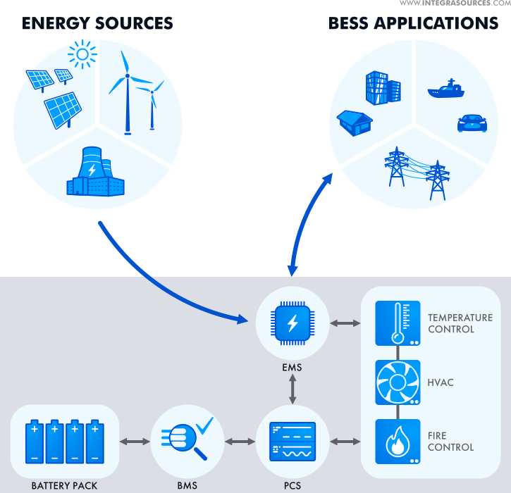
- Battery Energy Storage System (BESS):
- A BESS is a type of ESS that stores energy specifically in rechargeable electrochemical batteries. It captures energy from sources such as the electrical grid or renewable generation, stores it, and releases it when needed.
- A BESS typically includes:
- battery cells assembled into modules, packs/racks, or other battery assemblies (e.g., lithium-ion)
- a Battery Management System (BMS)
- a bidirectional Power Conversion System (PCS), typically an inverter/rectifier for AC-grid applications
- an Energy Management System (EMS) and/or higher-level control system
- protection and, depending on the design, thermal-management, monitoring, switching, and auxiliary systems
- “Battery energy storage system architecture” refers to the structural and functional integration of these subsystems into a complete, controllable solution, not just the batteries themselves.
- Hybridized Energy Storage System (HESS):
- A Hybrid Energy Storage System (HESS) combines two or more different energy-storage technologies or storage subsystems to leverage their complementary characteristics.
- This can improve overall system performance, power/energy capability, efficiency, operating range, or lifetime when appropriately designed and controlled, compared to a single storage technology.
- High-power components (e.g., supercapacitors) handle rapid, short-duration power demands or peaks
- High-energy components (e.g., batteries) handle longer-duration energy storage and supply
- Distributed Energy Storage Systems (DESS):
- Distributed Energy Storage Systems (DESS) are energy-storage resources deployed across multiple geographically distributed locations rather than in a single centralized facility.
- These systems can range from residential batteries to commercial, industrial, community, and utility-scale installations and are used to:
- store excess energy (e.g., from solar or wind)
- supply energy during peak demand
- provide grid services such as flexibility, voltage support, frequency regulation, or congestion management, where applicable
- improve grid resilience and operational flexibility
- DESS is a deployment/distribution model (where storage is located), not a specific storage technology.
- Galvanic Isolation:
- Galvanic Isolation is the electrical separation of two circuits or sections of an electrical system that prevents direct conductive current from flowing between them, while allowing electrical energy and/or signals to be transferred across an isolation barrier through non-conductive coupling mechanisms.
- By eliminating a direct conductive connection, galvanic isolation allows the separated circuits to operate at different electrical potentials and ground references. It is used to improve electrical safety, prevent ground loops and reduce the propagation of electrical disturbances between circuits.
- Energy or signals can be transferred across the isolation barrier through magnetic, optical or capacitive coupling. The isolation system must be designed to withstand the required operating voltages and electrical stresses of the application.
- Arc-Fault (the electrical fault (root cause)):
- An arc fault is an unintended electrical discharge that occurs when current flows through an ionized path between conductive points or across a damaged, interrupted or deteriorated electrical connection. It can result from damaged insulation, loose or corroded terminals, broken conductors, mechanical damage or contamination.
- Electrical arcing can generate intense localized heat and hot or molten particles that may ignite nearby combustible materials, creating a risk of electrical fire. Arc faults may be classified as series arc faults, which occur along a single conductor or connection, and parallel arc faults, which occur between conductors at different electrical potentials or between a conductor and ground.
- Some arc faults, particularly series arcs, may produce currents too low or irregular to trigger conventional overcurrent protection. They may also go undetected by residual current devices (RCDs) if the fault does not produce a sufficient residual current.
- Arc-Fault Detection Devices (AFDD):
- An arc-fault detection device (AFDD) is an electrical protective device designed to detect certain hazardous arc faults and disconnect the affected circuit to reduce the risk of fire. It uses electronic detection and signal-processing techniques to analyse electrical signals, such as current and, depending on the design, voltage, for patterns characteristic of arcing.
- AFDDs are designed to detect specified types of series and parallel arc faults that may not reliably trigger conventional overcurrent protection. Their detection capabilities and performance depend on the device design, applicable standards and electrical operating conditions.
- AFDDs are commonly installed in electrical distribution boards and are used in residential, commercial and other installations where required or recommended by applicable electrical regulations. They complement other protective devices, such as circuit breakers and RCDs, rather than replacing them.
- Arc Flash (the hazardous energy release event (consequence)):
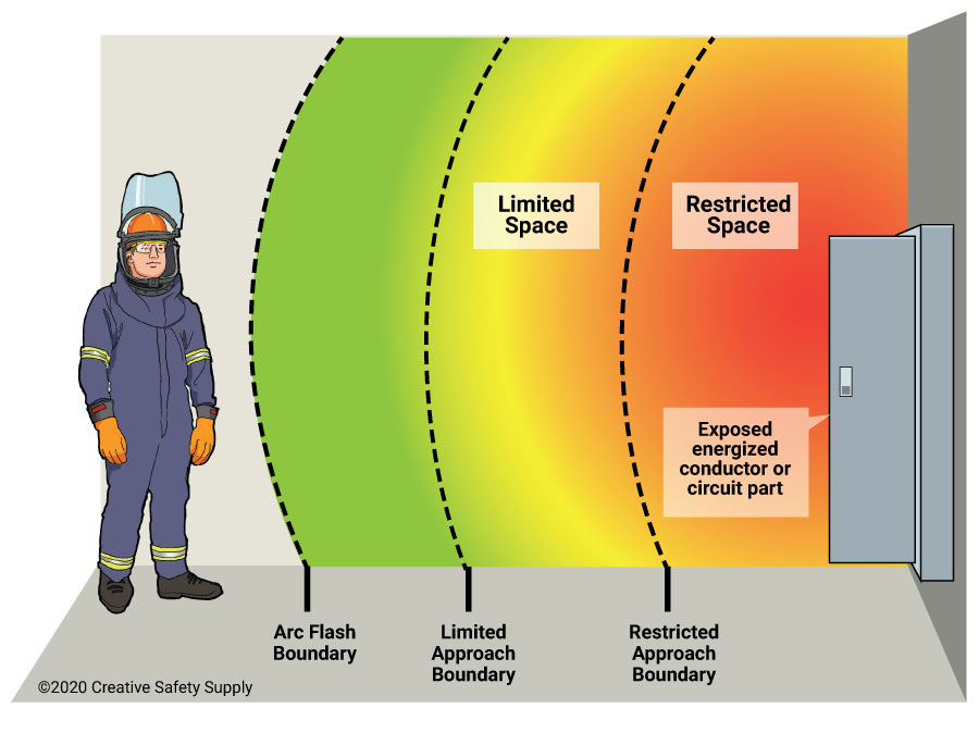
- An arc flash is a hazardous release of thermal energy produced by an electrical arc, typically when current flows through ionized air or another medium between conductors or between a conductor and ground. The arc can release intense heat and light and may produce hot gases, molten metal and, under certain conditions, a pressure wave or blast effect.
- An arc flash can cause severe burns, eye injuries, hearing damage and other serious or fatal injuries to people nearby. Its severity depends on factors including the available fault current, arc duration, system voltage, equipment configuration and the distance between the arc and the exposed person.
- Arc flashes may occur during electrical faults, equipment failure or certain switching and maintenance activities. Although an arc fault can initiate an arc flash, the terms describe different concepts: an arc fault is an electrical fault condition, while an arc flash is the hazardous energy-release event that may result.
- Arc Quenching:
- Arc quenching is the process of extinguishing an electrical arc, particularly during the opening of switching devices such as circuit breakers, contactors and switches. When contacts separate while current is flowing, an arc may form and continue conducting electricity until it is extinguished.
- Arc quenching methods are designed to reduce the arc’s energy and conductivity, for example by cooling the arc, lengthening or splitting it, increasing its resistance, or deionizing the arc path so that the insulating properties of the surrounding medium are restored. The specific mechanisms depend on the device’s design and operating principle.
- Common arc-quenching media include air, insulating oil, gases such as sulfur hexafluoride (SF₆), and vacuum. Different technologies use different approaches to interrupt current safely and withstand the recovery voltage across the separating contacts.
- The time required to extinguish an arc depends on the switching device, system frequency, current and circuit conditions. In AC systems, interruption often occurs at or near a natural current zero, while other designs use different interruption mechanisms. Arc extinction is one part of the overall switching or fault-clearing process.
- Carbon Dioxide (CO2):
- The primary greenhouse gas emitted through human activities. Carbon dioxide enters the atmosphere through the burning of fossil fuels (coal, natural gas, and oil), solid waste, biomass (e.g. wood), and also as a result of certain industrial chemical reactions (e.g. cement production).
- Carbon dioxide is removed from the atmosphere (or “sequestered”) when it is absorbed by plants as part of the biological carbon cycle and through ocean absorption and geological processes. In climate accounting, however, “carbon sequestration” generally refers to the removal and storage of carbon in a reservoir; natural uptake through the carbon cycle is not necessarily classified as anthropogenic carbon dioxide removal (CDR).
- CO₂ is naturally part of the carbon cycle, but human activities have significantly increased its concentration in the atmosphere.
- Biogenic Carbon Dioxide (CO2):
- Biogenic CO₂ and fossil-derived CO₂ are chemically identical molecules.
- The distinction is not chemical, but source-based:
- Biogenic carbon: CO₂ released from organic materials such as plants, wood, soil, and biomass that were recently part of the natural carbon cycle. Its accounting treatment depends on the applicable carbon-accounting methodology and whether the carbon is considered part of the contemporary biogenic carbon cycle.
- Fossil carbon: CO₂ released from fossil fuels (coal, oil, gas), which were stored underground for millions of years. This introduces additional carbon into the active atmospheric carbon cycle and is therefore generally treated as fossil CO₂ emissions.
- CO2e (Carbon Dioxide Equivalent):
- CO₂e means “carbon dioxide equivalent”.
- It is a standardized climate metric used to express the total climate impact of multiple greenhouse gases in a single standardized unit.
- CO₂e converts all greenhouse gases (such as methane and nitrous oxide) into the amount of CO₂ that would have the same integrated radiative forcing / climate impact over a defined time period using a specified Global Warming Potential (GWP) value.
- Formula: CO₂e = mass of gas × Global Warming Potential (GWP)
- Carbon dioxide equivalents are commonly expressed as million metric tonnes of carbon dioxide equivalents, abbreviated as MtCO₂e or Mt CO₂-eq; “MMTCDE” is used in some datasets but is not the preferred general notation.
- The carbon dioxide equivalent for a gas is derived by multiplying the tonnes of the gas by the associated GWP: CO₂e = mass of gas × GWP.
- For example, the GWP for methane is approximately 27–30 under IPCC AR6 depending on the methane source and accounting convention, while the 100-year GWP for nitrous oxide is 273. This means that emissions of 1 million metric tonnes of methane and nitrous oxide respectively would correspond to approximately 27–30 and 273 million metric tonnes of CO₂e under those GWP assumptions.
- Carbon Footprint:
- There is no universally agreed definition of what a carbon footprint is.
- The most widely used definition (GHG Protocol) describes it as: “The total set of greenhouse gas (GHG) emissions caused directly and indirectly through an organization’s operations and value chain.” The GHG Protocol generally refers to corporate GHG inventories and Scope 1, 2 and 3 emissions rather than prescribing one universal definition of “carbon footprint.”
- A carbon footprint is the total amount of greenhouse gas (GHG) emissions caused directly and indirectly by an individual, organization, product, or activity.
- It is typically measured in CO₂e.
- Decarbonization:
- Reduction of carbon dioxide emissions through the use of low-carbon energy sources and improved efficiency, with the goal of reducing overall greenhouse gas emissions. More broadly, decarbonization refers to reducing the carbon intensity and/or absolute greenhouse-gas emissions of an economy, sector, organization, product, or process, potentially including CO₂ removal for residual emissions.
- Decarbonization typically refers to system-wide transition, not only emission reduction at a single source.
- Carbon Credits or Carbon Offsets:
- Carbon credits are tradable certificates representing the verified reduction or removal of one metric tonne of CO₂e, generally generated by a specific project or activity; terminology and quality criteria vary between carbon markets.
- They are part of cap-and-trade systems, where:
- A cap limits total emissions
- Companies receive or buy emission allowances
- Excess allowances can be traded
- Offsets are often linked to external projects that reduce or remove emissions (e.g. reforestation, renewable energy). A carbon offset is generally a credit representing a reduction or removal outside the entity’s own emissions boundary that may be used to compensate for emissions, subject to the applicable programme or claim rules.
- Carbon credits and emission allowances should not be treated as synonymous: an allowance is a regulated authorization to emit under a cap-and-trade system, whereas a credit/offset generally represents a quantified emission reduction or removal.
- Carbon Capture and Storage (CCS) – Carbon Capture, Utilisation and Storage (CCUS):
- CCS involves capturing CO₂ emissions from industrial processes or other concentrated sources and storing them permanently in geological formations (e.g. underground reservoirs).
- CCUS adds a utilization step, where captured CO₂ is reused as a feedstock (e.g. fuels, chemicals, building materials). More precisely, CCUS refers to carbon capture followed by utilization and/or storage; utilization does not necessarily result in permanent carbon storage.
- CCS = capture + geological storage; CCUS = capture + utilization and/or storage.
- Carbon Dioxide Removal (CDR) or Durable Carbon Removal:
- CDR refers to methods that actively remove CO₂ from the atmosphere and store it for long periods in geological, biological, or mineral form. CDR specifically requires an anthropogenic activity that removes atmospheric CO₂ and durably stores it in geological, terrestrial, ocean, or product reservoirs.
- Examples include:
- Direct Air Capture (DAC)
- Bioenergy with Carbon Capture (BECCS)
- Enhanced Rock Weathering (ERW)
- CDR creates net negative emissions when removal exceeds emissions. A CDR activity itself can provide a net removal only when the total emissions associated with the removal process are lower than the amount of CO₂ durably removed and stored.
- Direct Air Capture (DAC):
- Technologies that extract CO2 directly from the atmosphere at any location, unlike carbon capture which is generally carried out at the point of emissions, such as a steel plant. DAC can capture CO₂ from ambient air regardless of where the original emissions occurred; it is distinct from point-source carbon capture.
- Constraints like costs and energy requirements as well as the potential for pollution make DAC a less desirable option for CO2 reduction. Its larger land footprint when compared to other mitigation strategies like carbon capture and storage systems (CCS) also put it at a disadvantage. However, DAC is a potential carbon-removal technology rather than simply a CO₂-reduction technology, and its climate benefit depends strongly on the energy source, capture efficiency, permanence of storage, and lifecycle emissions.
- Direct Air Capture and Storage (DACCS):
- Climate technology that removes carbon dioxide (CO2) directly from the ambient atmosphere using large fans and chemical processes to bind with the CO2. The captured CO₂ is then transported and durably stored, typically in geological formations.
- DACCS is therefore a specific form of CDR: DAC + durable CO₂ storage.
- Bioenergy with Carbon Capture and Storage (BECCS):
- Technology that generates energy from biomass while capturing and storing the resulting CO₂.
- Because biomass absorbs CO₂ while growing, BECCS can result in net negative emissions. It can result in net negative emissions when the full lifecycle emissions—including biomass production, harvesting, transport, processing, energy use, and capture/storage—are sufficiently lower than the amount of biogenic CO₂ durably removed from the atmosphere.
- Enhanced Rock Weathering (ERW):
- Carbon dioxide removal (CDR) technique that accelerates the natural process of rock weathering by grinding silicate rocks into dust and spreading it on land, typically agricultural fields. This process enhances reactions with water and atmospheric CO₂, converting dissolved carbon into bicarbonate and, ultimately, carbonate minerals or transporting dissolved inorganic carbon to aquatic systems, where it can be stored over long timescales.
- Its effectiveness and permanence depend on rock type, particle size, weathering rates, transport pathways, soil and water chemistry, and the emissions associated with mining, grinding, and transporting the rock.
- Limits of Carbon Dioxide Storage:
- Carbon storage is not endless; the Earth’s capacity for permanently storing vast amounts of captured carbon, particularly in geological formations, is limited, potentially reaching a critical limit of 1,460 gigatonnes at around 2200, though storage durations vary significantly depending on the method, from decades for some biological methods to potentially millions of years for others like mineralization. Estimates of geological storage capacity vary widely and depend on geology, reservoir characteristics, storage efficiency, infrastructure, economics, regulation, monitoring, and permanence.
- While some methods offer very long-term storage, the sheer volume needed to meet climate targets requires scaling up storage significantly beyond current capacity, raising concerns about the available volume over time. The practical constraint is therefore better described as the need to develop sufficient safe, permanent, economically and technically accessible storage capacity rather than a single known global physical limit.
- Carbon Impregnation:
- Carbon impregnation is the process of treating activated carbon with chemical agents (such as metals, acids, or bases) to enhance its ability to adsorb specific, hard-to-remove pollutants. By loading substances like silver, sulfur, or potassium hydroxide into its pores, this material combines physical adsorption with chemical reaction for improved, targeted filtration in water and air. This is a materials engineering process, not a climate accounting concept.
- Global Warming:
- Global warming is the long-term heating of Earth’s climate system observed since the pre-industrial period (between 1850 and 1900) due to human activities, primarily fossil fuel burning, which increases heat-trapping greenhouse gas levels in Earth’s atmosphere. Global warming refers specifically to the long-term increase in Earth’s average surface temperature; climate change is the broader term encompassing associated changes in climate systems, including precipitation, extremes, sea level, and ecosystems.
- Global Warming Potential (GWP):
- A measure of how much heat a greenhouse gas contributes to climate warming relative to CO₂ over a specific time period (commonly 100 years).
- CO₂ has a GWP of 1.
- GWP is the scientific basis for converting gases into CO₂e.
- GWP was developed to allow comparisons of the global warming impacts of different gases. The numerical GWP depends on the selected IPCC assessment, time horizon, and, for some gases such as methane, the emission source and accounting convention.
- Greenhouse Gas (GHG):
- Any gas that absorbs and emits infrared radiation in the atmosphere, contributing to the greenhouse effect.
- Main GHGs include:
- CO₂
- Methane (CH₄)
- Nitrous oxide (N₂O)
- Fluorinated gases such as HFCs, PFCs, SF₆ and NF₃
- Water vapor is a GHG but is not directly controlled by human emissions at scale. It is primarily a feedback in the climate system rather than a direct target of conventional anthropogenic GHG inventories.
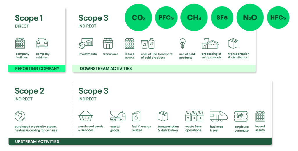
- GHG Protocol Corporate Standard Scope 1, 2 and 3: https://ghgprotocol.org/ + The GHG Protocol Corporate Accounting and Reporting Standard provides requirements and guidance for companies and other organizations preparing a corporate-level GHG emissions inventory. The Corporate Standard itself is voluntary, although companies may be required by applicable legislation or regulation to report using the GHG Protocol or equivalent requirements.
- Scope 1: Direct emissions:
- Direct emissions from company-owned and controlled resources. In other words, emissions are released into the atmosphere as a direct result of a set of activities, at a firm level. More precisely, Scope 1 covers direct GHG emissions from sources that are owned or controlled by the reporting organization.
- It is divided into four categories:
- Stationary combustion (e.g from fuels, heating sources). All fuels that produce GHG emissions must be included in scope 1. This applies when the combustion source is owned or controlled by the reporting organization.
- Mobile combustion is all vehicles owned or controlled by a firm, burning fuel (e.g. cars, vans, trucks). The increasing use of “electric” vehicles (EVs), means that some of the organisation’s fleets could fall into Scope 2 emissions. For example, fuel combustion in an owned/controlled vehicle is Scope 1, whereas electricity purchased to charge an EV is generally Scope 2; an EV itself does not create Scope 2 emissions—the purchased electricity does.
- Fugitive emissions are leaks from greenhouse gases (e.g. refrigeration, air conditioning units). It is important to note that refrigerant gases are not uniformly “a thousand times more dangerous” than CO₂; some refrigerants have GWPs of hundreds or thousands of times that of CO₂, while others have much lower values. Companies are encouraged to report these emissions.
- Process emissions are released during industrial processes, and on-site manufacturing (e.g. production of CO2 during cement manufacturing, factory fumes, chemicals). These are direct emissions resulting from physical or chemical processes other than fuel combustion, such as calcination in cement production..
- Scope 2: Indirect emissions – owned:
- Indirect emissions from the generation of purchased energy, from a utility provider. In other words, all GHG emissions released in the atmosphere, from the consumption of purchased electricity, steam, heat and cooling. Scope 2 covers indirect GHG emissions associated with the generation of purchased or acquired electricity, steam, heat, and cooling consumed by the reporting organization; “owned” is therefore misleading because the emissions source is owned or controlled by another entity.
- For most organisations, electricity will be the unique source of scope 2 emissions. Simply stated, the energy consumed falls into two scopes: Scope 2 covers the electricity consumed by the end-user. Scope 3 covers the energy used by the utilities during transmission and distribution (T&D) losses. More precisely, Scope 2 covers the generation-related emissions associated with purchased electricity, not the physical electricity itself. T&D losses are generally accounted for in Scope 3 Category 3 for an energy consumer that does not own the T&D system, although the treatment can vary depending on ownership and accounting circumstances.
- Scope 3: Indirect emissions – not owned:
- Indirect emissions – not included in scope 2 – that occur in the value chain of the reporting company, including both upstream and downstream emissions. In other words, emissions are linked to the company’s operations. According to the GHG protocol, scope 3 emissions are separated into 15 categories. Scope 3 therefore captures other indirect value-chain emissions, upstream and downstream, across the 15 defined categories of the Scope 3 Standard.
- Scope 1: Direct emissions:
- Grid, Microgrids, DERs and DERM’s:
- Grid / Power Grid:
- The power grid is a network for delivering electricity to consumers. The power grid includes power generation facilities, substations, transmission lines and towers, distribution networks, protection and control equipment, and associated communication and monitoring infrastructure.
- The grid continuously balances electricity generation and consumption while maintaining system stability and power quality, supplying electricity for applications ranging from industry to household appliances.
- Electric grids perform three major functions or stages of electricity supply: power generation, transmission, and distribution. Grid operation also includes functions such as system balancing, protection, control, monitoring, and, increasingly, energy storage and demand-side management.
- The power grid is a network for delivering electricity to consumers. The power grid includes power generation facilities, substations, transmission lines and towers, distribution networks, protection and control equipment, and associated communication and monitoring infrastructure.
- Microgrid:
- A microgrid is a group of interconnected loads and distributed energy resources (DERs) within clearly defined electrical boundaries that acts as a single controllable entity with respect to the main grid and can operate either connected to the main grid or, when appropriately designed, intentionally and controllably in an islanded mode.
- Microgrids can integrate local generation, energy storage, controllable loads, and other DERs to improve resilience, flexibility, efficiency, or local energy management.
- A microgrid is a group of interconnected loads and distributed energy resources (DERs) within clearly defined electrical boundaries that acts as a single controllable entity with respect to the main grid and can operate either connected to the main grid or, when appropriately designed, intentionally and controllably in an islanded mode.
- Smart Grid:
- A smart grid is an electrical grid enhanced with digital communications, sensing, automation, control, and data/analytics technologies across generation, transmission, distribution, and/or customer-side systems to improve the monitoring, operation, efficiency, reliability, resilience, and flexibility of the power system.
- Distributed Energy Resources (DERs):
- Distributed energy resources (DERs) are relatively small-scale electricity generation, storage, and flexible demand resources, located at or near the distribution system or customer premises, that can supply, store, or modify electricity consumption and are interconnected to the electric grid. They are often located close to load centers and can be used individually or in aggregate to provide value to the grid.
- Common examples of DERs include rooftop solar PV units, small wind turbines, small gas-fired generators or engines/turbines, microturbines, biomass generators, fuel cells, combined heat and power (CHP) or tri-generation systems with electrical generation, battery storage, electric vehicles and controllable EV charging or discharging where they can provide grid flexibility, and demand response applications.
- Distributed energy resources (DERs) are relatively small-scale electricity generation, storage, and flexible demand resources, located at or near the distribution system or customer premises, that can supply, store, or modify electricity consumption and are interconnected to the electric grid. They are often located close to load centers and can be used individually or in aggregate to provide value to the grid.
- Distributed Energy Resources Management Systems (DERMS):
- Distributed Energy Resources Management Systems (DERMS) are software platforms that help utilities, distribution system operators (DSOs), aggregators, and other energy-sector organizations monitor, provide visibility into, forecast, coordinate, optimize, and, where supported, control distributed energy resources (DERs).
- DERMS can be used to aggregate and coordinate large numbers of DERs and flexible loads for grid services, including voltage and power-flow management, congestion and constraint management, balancing, flexibility services, resilience, and participation in demand-response or other electricity markets. DERMS can be defined in many ways, depending on the use case, the types of DERs being managed, the responsibilities of the organization using the system, and the architecture of the power system.
- Distributed Energy Resources Management Systems (DERMS) are software platforms that help utilities, distribution system operators (DSOs), aggregators, and other energy-sector organizations monitor, provide visibility into, forecast, coordinate, optimize, and, where supported, control distributed energy resources (DERs).
- Grid / Power Grid:
- LED:
- LED stands for Light Emitting Diode. An LED is a semiconductor light-emitting device that produces light through electroluminescence when electrically biased. LED lighting products can provide substantially higher luminous efficacy than incandescent and halogen lighting technologies. How do they work? When a suitable semiconductor p–n junction is forward biased, electrons and holes recombine in the active region, releasing energy as photons; this process is known as electroluminescence.
- A light-emitting diode is a semiconductor light source that emits light when electrical current flows through its appropriately biased junction. Electrons in the semiconductor recombine with holes, releasing energy in the form of photons. The wavelength and therefore the color of the emitted light depend primarily on the semiconductor materials, bandgap and device structure. In practical LED lighting products, the LED or LED array is typically combined with a driver, optics, thermal-management components and mechanical elements to form a lamp or luminaire.
- LED vs. Halogen:
- Halogen bulbs, while lasting longer than traditional incandescent bulbs, typically have rated lives of around 2,000 hours, although this varies by lamp type and application. In contrast, LED lamps and luminaires can commonly have useful or rated lives of tens of thousands of hours, depending on the product and the applicable lifetime metric. For LED products, useful life is often specified using lumen maintenance—for example, L70, the operating time at which light output is expected to reach 70% of its initial value—rather than simply the time until complete failure. LED lighting can use substantially less electricity than halogen lighting for comparable light output, although the actual saving depends on the products and operating conditions being compared.
- Compared with halogen lighting, LED lights are generally more energy-efficient, have longer useful lives, and offer a wider range of controllable characteristics such as color temperature, dimming and color quality. They often have a higher upfront purchase cost, but their lower energy consumption and longer service life can reduce total cost of ownership over time. LED products also generally require less frequent replacement, although driver and other component failures can occur before the LED light source reaches its lumen-maintenance limit.
- OLED:
- An Organic Light-Emitting Diode (OLED) is a solid-state electroluminescent device consisting of one or more thin layers of organic semiconductor material between electrodes that emits light when an appropriate electrical voltage is applied. At least one electrode must be transparent or sufficiently light-transmissive for light to be emitted from the device.
- OLED devices (including television screens, computer monitors, smartphones and other display systems) use organic semiconductor material as a light-emitting layer. Organic LEDs can produce high-quality displays with high contrast, wide viewing angles and very low black luminance because individually addressable OLED pixels can be switched off. OLED technology is widely used for high-quality displays, although its performance characteristics involve trade-offs such as cost, lifetime, maximum brightness, power consumption and susceptibility to image retention or burn-in depending on the application and implementation.
- microLED:
- Compared to conventional LCD technology, microLED displays can offer very high brightness, high contrast, fast response times and potentially high energy efficiency. They are also capable of rapid modulation and have been investigated for specialized applications such as high-speed optical communication.
- MicroLED displays use microscopic inorganic LEDs as individually addressable light-emitting pixels or subpixels and can combine very high brightness, high contrast, fast response and potentially high energy efficiency. Unlike OLED, the light-emitting elements are inorganic LEDs. MicroLED displays have demonstrated very high brightness in prototype and commercial implementations, although performance, efficiency, lifetime, manufacturing complexity and cost vary significantly between architectures and products. MicroLED therefore remains an important emerging display technology.