Siemens – Largest Siemens location worldwide completed
- Consolidation of Siemens locations in Nuremberg metropolitan area now largely finished
- Siemens Campus Erlangen to bring together people and expertise from all Siemens units at one location and strengthen collaboration in line with ONE Tech Company strategy
- Model for sustainable transformation of former research center into open and vibrant urban district
- Module 8 to open as final building block of Siemens Campus Erlangen
One of the largest transformation projects in Siemens’ recent history is now finished. The opening of the new buildings in Module 8 marks the completion of Siemens Campus Erlangen, which consolidates all company’s locations in and around Nuremberg, Germany. The project demonstrates how a former research center can be transformed into an open, sustainable urban district and a modern campus. Since 2014, Siemens has invested around €1 billion in the campus, where approximately 16,000 people from the greater Nuremberg metropolitan region work for the company today. With construction of the Siemens Technology Campus at the company’s development and manufacturing site along the Erlangen European Canal having started last year, Siemens is already continuing this development, further investing in Erlangen as an innovation hub and reaffirming its commitment to Germany as a business location as well as to the “Made for Germany” initiative.
An area that was once accessible only to Siemens people is now a space transparent and open to all.
A total of 18 new buildings – including a reception hall and a laboratory – have been built. All of Siemens’ operating businesses are represented on the campus, including Siemens Foundational Technologies, which conducts research, the company’s Middle Franconia Branch Office, which supports customers and partners in the region, and Siemens Professional Education, which provides training and education. Restaurants and shops make the location a popular meeting place not only for Siemens people but also for all the residents of Erlangen.
“With Siemens Campus Erlangen, a vision has become reality. The campus stands for innovation, collaboration and sustainability, demonstrating how modern working environments and urban development can successfully go hand in hand. This is where interdisciplinary teams create the technologies and solutions of tomorrow. The campus makes visible what defines Siemens as a ONE Tech Company: the combination of technology, expertise and collaboration across all business areas,” said Veronika Bienert, Chief Financial Officer of Siemens AG and member of the Managing Board with responsibility for the Nuremberg metropolitan region.

Opening Ceremony: Module 8 was officially opened with a bang. From left to right: Martin Jandt, Jörg Volleth, Veronika Bienert, Jörg Vocke, Rainer Brehm, Christian Eichinger, Michael Six. Pressebild Modul8.jpg
Modern working environments and sustainability in focus
Siemens Campus Erlangen combines modern working environments with high sustainability standards. Renewable energy sources, rainwater utilization, green roofs and intelligent building technology enable near carbon-neutral operation. At the same time, the buildings have continuously evolved – from conventional construction methods to timber-hybrid structures and all-electric buildings using low-carbon construction materials.
“With Module 8, Siemens Digital Industries is gaining a new home at Siemens Campus Erlangen. Here, we’re bringing together our expertise in automation and industrial software while fostering collaboration with other Siemens units, research institutions, customers and partners. This project strengthens our innovative power as a ONE Tech Company and is also a clear commitment to a location known worldwide as the epicenter of automation,” said Cedrik Neike, member of the Managing Board of Siemens AG and CEO of Digital Industries.
The result is a vibrant space that fosters innovation, encourages interaction and makes a sustainable contribution to the urban development of the City of Erlangen, which has constructively supported this major project from the very beginning.
“The Siemens Campus is a clear and long-term commitment by Siemens to Erlangen as a business location,” said Jörg Volleth, Mayor of Erlangen, at the opening ceremony. “It strengthens our city as an international center for science and business and demonstrates how innovation, modern working environments and sustainable urban development can successfully work together. I’m particularly pleased that we’ll continue this journey together: with the planned ‘Südquartier’, much-needed housing for families, students and skilled professionals will be created in the coming years. This initiative will result in an open and vibrant district that combines working, living and community life – a benefit for the entire city.”
With the opening of Module 8, Siemens Campus Erlangen is now complete. The project was led by Siemens Real Estate, Siemens’ real estate arm, and is now regarded as a blueprint for transforming former industrial and research locations into open and sustainable urban districts. Many of the concepts and technologies tested in Erlangen are already being incorporated into the development of other Siemens locations around the world.
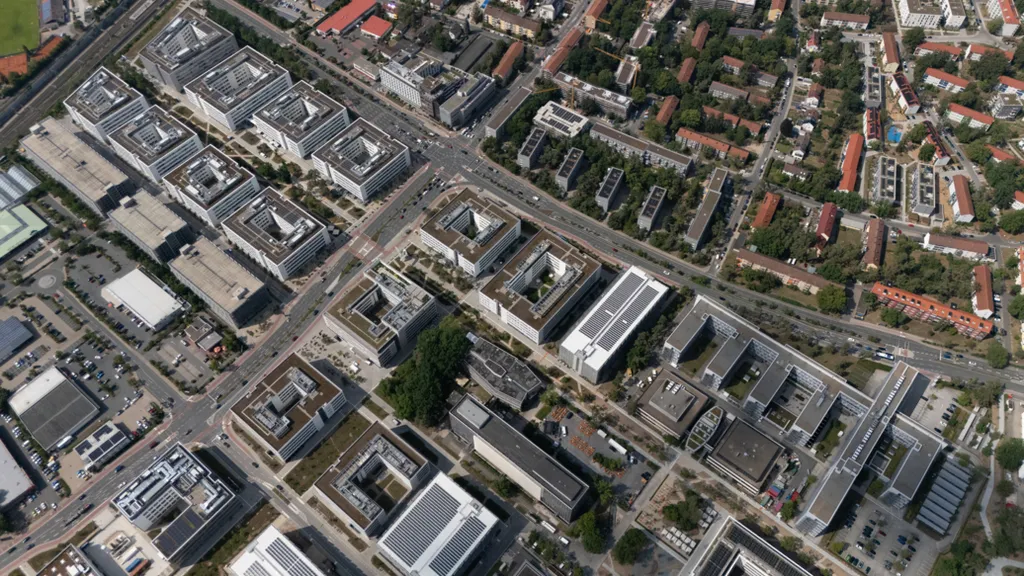
All Siemens units are connected within a single campus. Approximately 16,000 Siemens employees work in buildings along a 2 km long green spine on the campus.
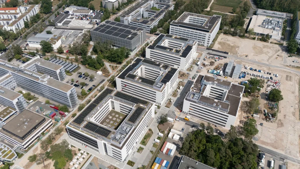
Approximately 70,000 m² of new office space has been created in four state-of-the-art, carbon neutral “all electric buildings” (three of which have been completed), which are heated and cooled exclusively by heat pumps.

Sustainability has fundamental part of the campus since the project began. Solar power systems with the peak capacity of approximately 2 MW have been installed on roofs and façades.
SourceSiemens
EMR Analysis
More information on Siemens AG: See full profile on EMR Executive Services
More information on Dr. Roland Busch (President and Chief Executive Officer, Siemens AG): See full profile on EMR Executive Services
More information on Veronika Bienert (Member of the Managing Board and Chief Financial Officer, Siemens AG): See full profile on EMR Executive Services
More information on “ONE Tech Company” Program by Siemens AG: See full profile on EMR Executive Services
More information on Siemens Foundational Technologies by Siemens AG: https://www.siemensvyvojar.cz/en/ + Siemens Foundational Technologies is an internal development centre engaged in research and development for the Siemens Group worldwide. Our Siemens Foundational Technologies team in the Czech Republic comprises more than 500 developers in three locations: Prague, Brno, and Pilsen. We are primarily involved in developing new and end-to-end products (software, hardware development, mechanics, testing). We engineer robust designs and solutions for industry with a lifetime for decades, which can also be deployed under harsh conditions such as drilling platforms. In addition, we develop end-to-end solutions in digitisation and the Internet of Things (IoT).
More information on Dr. Ulrich Förster (Head of, Siemens Foundational Technologies, Siemens AG + Chief Executive Officer, Siemens Advanta Development, Siemens Advanta, Siemens AG): See full profile on EMR Executive Services
More information on Siemens Professional Education (SPE) by Siemens AG: https://www.siemens.com/en-us/company/jobs/growth-careers/siemens-professional-education/ + Educating global talents in electrical engineering, mechatronics, computer science and industrial engineering through dual programs ensures a skilled future workforce. Our hands-on learning covers IoT, AI and sustainability, blending theory and practice with top industry partners.
More information on Bettina Weckesser (Head of, Siemens Professional Education, Siemens AG): See full profile on EMR Executive Services
More information on Siemens Digital Industries (DI) by Siemens AG: See full profile on EMR Executive Services
More information on Cedrik Neike (Member of the Managing Board and Chief Executive Officer, Siemens Digital Industries (DI), Siemens AG): See full profile on EMR Executive Services
More information on Siemens Real Estate (SRE) by Siemens AG: https://www.siemens.com/global/en/company/about/businesses/real-estate.html + Siemens Real Estate Services (Service & Governance): Specializes in solutions for the operation of office, industrial and specialized buildings. Siemens Real Estate (SRE) offers Siemens as well as external customers holistic solutions for the entire real estate lifecycle – from strategy to development to operation. As a pioneer in corporate real estate management, SRE drives the transformation of office and production sites around the globe and significantly increases the efficiency and flexibility of its customers. This embraces the implementation of innovative workplace concepts that support future -oriented hybrid working, as well as the use of intelligent and sustainable solutions to strengthen the future viability and resilience of industrial sites. As such, SRE is also making a substantial contribution to the company’s target of being carbon neutral by 2030.
No longer reported since 2022. Transferred to the item Financing, eliminations and other items.
More information on Jörg Vocke (Chief Executive Officer, Siemens Real Estate (SRE), Siemens AG): See the full profile on EMR Executive Services
More information on the “Made for Germany” Initiative: https://www.db.com/news/detail/20250721-61-companies-launch-made-for-germany-initiative-to-boost-germany-s-future-as-a-global-economic-powerhouse + “Made for Germany” is a cross-industry initiative, in which 61 leading companies and investors join forces for a strong, successful, and future-proof German economy. The initiative aims to foster constructive dialogue between business, the government and society in order to boost confidence in Germany as an economic hub, attract targeted investment, and stimulate domestic demand. Ultimately, this will create lasting opportunities for future generations.
- 631 billion euros (~733 billion US dollars) in pledged investments for Germany by 2028
- Pioneering flagship projects to drive innovation, generate employment, and boost competitiveness
- “Made for Germany” seeks to establish a new and strengthened dialogue between business and government, aiming to enhance the country’s investment climate
More information on Friedrich Merz (Federal Chancellor, Germany): https://www.bundesregierung.de/breg-en/federal-cabinet/cv-2343398 + https://www.linkedin.com/in/friedrich-merz/
More information on Jörg Volleth (Mayor, Erlangen, Germany): https://erlangen.de/themenseite/mitgestalten/politik-mitgestalten/oberbuergermeister-joerg-volleth + https://www.linkedin.com/in/j%C3%B6rg-volleth-09b20723a/
EMR Additional Notes:
- Carbon Dioxide (CO2):
- The primary greenhouse gas emitted through human activities. Carbon dioxide enters the atmosphere through the burning of fossil fuels (coal, natural gas, and oil), solid waste, biomass (e.g. wood), and also as a result of certain industrial chemical reactions (e.g. cement production).
- Carbon dioxide is removed from the atmosphere (or “sequestered”) when it is absorbed by plants as part of the biological carbon cycle and through ocean absorption and geological processes.
- CO₂ is naturally part of the carbon cycle, but human activities have significantly increased its concentration in the atmosphere.
- Biogenic Carbon Dioxide (CO2):
- Biogenic CO₂ and fossil-derived CO₂ are chemically identical molecules.
- The distinction is not chemical, but source-based:
- Biogenic carbon: CO₂ released from organic materials such as plants, wood, soil, and biomass that were recently part of the natural carbon cycle.
- Fossil carbon: CO₂ released from fossil fuels (coal, oil, gas), which were stored underground for millions of years.
- CO2e (Carbon Dioxide Equivalent):
- CO₂e means “carbon dioxide equivalent”.
- It is a standardized climate metric used to express the total climate impact of multiple greenhouse gases in a single standardized unit.
- CO₂e converts all greenhouse gases (such as methane and nitrous oxide) into the amount of CO₂ that would have the same global warming effect over a defined time period.
- Formula: CO₂e = mass of gas × Global Warming Potential (GWP)
- Carbon dioxide equivalents are commonly expressed as million metric tonnes of carbon dioxide equivalents, abbreviated as MMTCDE.
- The carbon dioxide equivalent for a gas is derived by multiplying the tonnes of the gas by the associated GWP: MMTCDE = (million metric tonnes of a gas) * (GWP of the gas).
- For example, the GWP for methane is 25 and for nitrous oxide 298. This means that emissions of 1 million metric tonnes of methane and nitrous oxide respectively is equivalent to emissions of 25 and 298 million metric tonnes of carbon dioxide.
- Carbon Footprint:
- There is no universally agreed definition of what a carbon footprint is.
- The most widely used definition (GHG Protocol) describes it as: “The total set of greenhouse gas (GHG) emissions caused directly and indirectly through an organization’s operations and value chain.”
- A carbon footprint is the total amount of greenhouse gas (GHG) emissions caused directly and indirectly by an individual, organization, product, or activity.
- It is typically measured in CO₂e.
- Decarbonization:
- Reduction of carbon dioxide emissions through the use of low-carbon energy sources and improved efficiency, with the goal of reducing overall greenhouse gas emissions.
- Decarbonization typically refers to system-wide transition, not only emission reduction at a single source.
- Carbon Credits or Carbon Offsets:
- Carbon credits are tradable certificates representing the right to emit one metric ton of CO₂e.
- They are part of cap-and-trade systems, where:
- A cap limits total emissions
- Companies receive or buy allowances
- Excess credits can be traded
- Offsets are often linked to external projects that reduce or remove emissions (e.g. reforestation, renewable energy).
- Carbon Capture and Storage (CCS) – Carbon Capture, Utilisation and Storage (CCUS):
- CCS involves capturing CO₂ emissions from industrial processes and storing them permanently in geological formations (e.g. underground reservoirs).
- CCUS adds a utilization step, where captured CO₂ is reused as a feedstock (e.g. fuels, chemicals, building materials).
- CCS = storage only, CCUS = storage + reuse.
- Carbon Dioxide Removal (CDR) or Durable Carbon Removal:
- CDR refers to methods that actively remove CO₂ from the atmosphere and store it for long periods in geological, biological, or mineral form.
- Examples include:
- Direct Air Capture (DAC)
- Bioenergy with Carbon Capture (BECCS)
- Enhanced Rock Weathering (ERW)
- CDR creates net negative emissions when removal exceeds emissions.
- Direct Air Capture (DAC):
- Technologies that extract CO2 directly from the atmosphere at any location, unlike carbon capture which is generally carried out at the point of emissions, such as a steel plant.
- Constraints like costs and energy requirements as well as the potential for pollution make DAC a less desirable option for CO2 reduction. Its larger land footprint when compared to other mitigation strategies like carbon capture and storage systems (CCS) also put it at a disadvantage.
- Direct Air Capture and Storage (DACCS):
- Climate technology that removes carbon dioxide (CO2) directly from the ambient atmosphere using large fans and chemical processes to bind with the CO2.
- Bioenergy with Carbon Capture and Storage (BECCS):
- Technology that generates energy from biomass while capturing and storing the resulting CO₂.
- Because biomass absorbs CO₂ while growing, BECCS can result in net negative emissions.
- Enhanced Rock Weathering (ERW):
- Carbon dioxide removal (CDR) technique that accelerates the natural process of rock weathering by grinding silicate rocks into dust and spreading it on land, typically agricultural fields. This process uses rainwater to convert atmospheric carbon dioxide into mineral carbonates, which are then stored long-term in soils, groundwater, and oceans.
- Limits of Carbon Dioxide Storage:
- Carbon storage is not endless; the Earth’s capacity for permanently storing vast amounts of captured carbon, particularly in geological formations, is limited, potentially reaching a critical limit of 1,460 gigatonnes at around 2200, though storage durations vary significantly depending on the method, from decades for some biological methods to potentially millions of years for others like mineralization. While some methods offer very long-term storage, the sheer volume needed to meet climate targets requires scaling up storage significantly beyond current capacity, raising concerns about the available volume over time.
- Carbon Impregnation:
- Carbon impregnation is the process of treating activated carbon with chemical agents (such as metals, acids, or bases) to enhance its ability to adsorb specific, hard-to-remove pollutants. By loading substances like silver, sulfur, or potassium hydroxide into its pores, this material combines physical adsorption with chemical reaction for improved, targeted filtration in water and air. This is a materials engineering process, not a climate accounting concept.
- Global Warming:
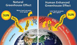
- Global warming is the long-term heating of Earth’s climate system observed since the pre-industrial period (between 1850 and 1900) due to human activities, primarily fossil fuel burning, which increases heat-trapping greenhouse gas levels in Earth’s atmosphere.
- Global Warming Potential (GWP):
- A measure of how much heat a greenhouse gas traps in the atmosphere compared to CO₂ over a specific time period (commonly 100 years).
- CO₂ has a GWP of 1.
- GWP is the scientific basis for converting gases into CO₂e.
- GWP was developed to allow comparisons of the global warming impacts of different gases.
- Greenhouse Gas (GHG):
- Any gas that absorbs and traps infrared radiation in the atmosphere, contributing to the greenhouse effect.
- Main GHGs include:
- CO₂
- Methane (CH₄)
- Nitrous oxide (N₂O)
- Fluorinated gases
- Water vapor is a GHG but is not directly controlled by human emissions at scale.
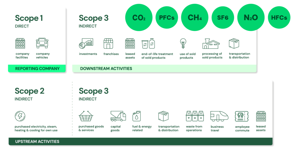
- GHG Protocol Corporate Standard Scope 1, 2 and 3: https://ghgprotocol.org/ + The GHG Protocol Corporate Accounting and Reporting Standard provides requirements and guidance for companies and other organizations preparing a corporate-level GHG emissions inventory. Scope 1 and 2 are typically mandatory for companies that are required to report their emissions by national or regional regulations. The GHG Protocol itself is a voluntary standard.
- Scope 1: Direct emissions:
- Direct emissions from company-owned and controlled resources. In other words, emissions are released into the atmosphere as a direct result of a set of activities, at a firm level. It is divided into four categories:
- Stationary combustion (e.g from fuels, heating sources). All fuels that produce GHG emissions must be included in scope 1.
- Mobile combustion is all vehicles owned or controlled by a firm, burning fuel (e.g. cars, vans, trucks). The increasing use of “electric” vehicles (EVs), means that some of the organisation’s fleets could fall into Scope 2 emissions.
- Fugitive emissions are leaks from greenhouse gases (e.g. refrigeration, air conditioning units). It is important to note that refrigerant gases are a thousand times more dangerous than CO2 emissions. Companies are encouraged to report these emissions.
- Process emissions are released during industrial processes, and on-site manufacturing (e.g. production of CO2 during cement manufacturing, factory fumes, chemicals).
- Direct emissions from company-owned and controlled resources. In other words, emissions are released into the atmosphere as a direct result of a set of activities, at a firm level. It is divided into four categories:
- Scope 2: Indirect emissions – owned:
- Indirect emissions from the generation of purchased energy, from a utility provider. In other words, all GHG emissions released in the atmosphere, from the consumption of purchased electricity, steam, heat and cooling. For most organisations, electricity will be the unique source of scope 2 emissions. Simply stated, the energy consumed falls into two scopes: Scope 2 covers the electricity consumed by the end-user. Scope 3 covers the energy used by the utilities during transmission and distribution (T&D losses).
- Scope 3: Indirect emissions – not owned:
- Indirect emissions – not included in scope 2 – that occur in the value chain of the reporting company, including both upstream and downstream emissions. In other words, emissions are linked to the company’s operations. According to the GHG protocol, scope 3 emissions are separated into 15 categories.
- Scope 1: Direct emissions:
- Blueprint:
- A blueprint is a detailed technical drawing or plan used to design and construct something, serving as a guide that can be followed during implementation. Want to build the best tree house ever? Draw up a blueprint and follow the design carefully.
- The literal meaning of a blueprint refers to a historical reproduction process in which technical drawings were printed as white lines on a blue background. After the paper was washed and dried to fix the image, the result was a negative image of white lines against a dark blue background—hence the name “blueprint.”
- By definition, a blueprint is a detailed plan, design, or model that specifies all necessary components and their relationships before execution.
- The blueprint perspective allows you to see how all elements fit together structurally and functionally before building or implementation begins (not only “what pieces are needed”).
- Heat Exchangers, Heat Pumps, Air Source Heat Pump (ASHP), Hydronics, Geothermal Heating – Cooling & Chillers:
- Heat Exchangers – Heat Transfer Foundation:
- Used to transfer heat from one medium to another. These media may be a gas, liquid, or a combination of both. The media may be separated by a solid wall to prevent mixing or may be in direct contact. Heat exchangers are required to provide heating and/or cooling to meet a process requirement.
- In HVAC, heat exchangers are used to transfer heat between the indoor and outdoor air streams while keeping them physically separated as a means of cooling or heating indoor air. heat exchangers are components; systems performing heating/cooling cycles are heat pumps, not the heat exchangers themselves.
- Gasketed heat exchangers are compact, highly efficient devices used to transfer heat between two fluids without mixing them. They consist of a series of corrugated metal plates fitted with elastomeric gaskets that seal the channels and direct the fluids into alternate pathways. This design creates high turbulence, maximizing heat transfer efficiency while maintaining a significantly smaller footprint than traditional shell-and-tube units.
- Heat Pumps – Thermodynamic Systems (Energy Transfer Devices):
- Use electricity to transfer heat from a cool space to a warm space, making the cool space cooler and the warm space warmer. During the heating season, heat pumps move heat from the cool outdoors into your warm house. During the cooling season, heat pumps move heat from your house into the outdoors. Because they transfer heat rather than generate heat, heat pumps can efficiently provide comfortable temperatures for your home. They operate on a vapor-compression refrigeration cycle (similar to air conditioners and chillers).
- Air Source Heat Pump (ASHP) – Thermodynamic Systems (Energy Transfer Devices):
- Heating and cooling system that extracts heat from the outside air and transfers it to a building’s interior for heating, or reverses the process to cool the building. ASHPs are a low-carbon alternative to traditional heating systems like gas boilers or oil furnaces. They are efficient because they transfer heat rather than generating it, typically providing a coefficient of performance (COP) of ~2–4 under typical conditions (can vary significantly with temperature).
- The only difference between a heat pump and a chiller is that one is designed to remove heat from a space or process stream, making it cooler and rejecting heat to the environment, while the other is designed to extract heat from the environment and use it to provide useful heat.
- Chillers – Cooling Systems (Heat Removal Focus):
- Mechanical systems that remove heat from a building’s liquid coolant, typically water, and transfer it to another location to cool the air and maintain comfort. Unlike traditional systems that might cool air directly, chillers generate chilled water that circulates through air handling units (AHUs) within the space to absorb heat, making them essential for cooling large commercial or industrial buildings.
- Chillers and heat pumps use similar thermodynamic cycles, but are designed and optimized for different applications (process/central cooling vs reversible heating/cooling).
- The only difference between a heat pump and a chiller is not strictly the function, but primarily the design intent and system integration:
- A chiller is typically designed to remove heat from a space or process (cooling-focused).
- A heat pump is designed to provide useful heating (and often reversible cooling).
- Hydronics – Distribution Systems (Energy Transport):
- Systems of heating or cooling that involves transfer of heat by a circulating fluid (such as water or vapor) in a closed system of pipes. Hydronic systems distribute thermal energy (heating or cooling) but do not generate it themselves.
- Geothermal Heating and Cooling Systems – Renewable / Ground-Based Systems:
- Take advantage of the relatively stable temperature underground using a piping system, commonly referred to as a “loop.” Water or a water-antifreeze mixture circulates in the loop to exchange heat between your home, the ground source heat pump, and the earth, providing geothermal heating, cooling, and hot water at very high efficiencies (often higher than ASHPs).
- Heat Exchangers – Heat Transfer Foundation:
- Fundamental Units of Electricity:
- Electric Current:
- Ampere – Amp (A):
- Amperes measure the flow of electrical current (electric charge) through a circuit. Ampere (A) is the SI unit of measure for the rate of electron flow, or current, in an electrical conductor.
- One ampere is defined as one coulomb of electric charge moving past a point in one second (1 A = 1 C/s). The ampere is named after the French physicist André-Marie Ampère, who made significant contributions to the study of electromagnetism.
- Milliampere (mA):
- Milliampere (mA) is a unit of electric current equal to one-thousandth of an ampere (1 mA = 0.001 A = 10⁻³ A). The prefix “milli” signifies 10⁻³ in the metric system. This unit is commonly used to measure small currents in electronic circuits and consumer devices.
- Ampere – Amp (A):
- Electrical Potential (Voltage):
- Volt (V):
- Volts measure the electric potential difference that drives the flow of electrons through a circuit. Voltage can be thought of as the “electrical pressure” that pushes current through a conductor.
- Kilovolt (kV):
- Kilovolt (kV) is a unit of potential difference equal to 1,000 volts (1 kV = 1,000 V).
- Volt (V):
- Electrical Power vs. Electrical Energy:
- Watts measure the rate of energy consumption or generation, also known as power.
- A useful analogy is:
- Power = the speed at which electricity is used or generated
- Energy = the total amount of electricity used or generated over time
- Power vs. Energy: how electricity is measured and billed.
- Power (measured in W, kW, MW, GW, TW): Rate at which energy is used or generated at a given moment.
- Energy (measured in Wh, kWh, MWh, GWh, TWh): Total amount of power consumed or generated over a period of time (Energy = Power × Time).
- Real Power Units:
- Real power units measure the actual (active) power that performs useful work.
- Kilowatt (kW):
- A kilowatt is simply a measure of how much power an electric appliance consumes—it’s 1,000 watts to be exact.
- You can quickly convert watts (W) to kilowatts (kW) by dividing your wattage by 1,000:
- 1,000 W = 1 kW
- Megawatt (MW):
- One megawatt equals one million watts or 1,000 kilowatts, roughly enough electricity for the instantaneous demand of approximately 500–1,000 homes (depending on region and consumption patterns).
- Gigawatt (GW):
- A gigawatt (GW) is a unit of power, and it is equal to one billion watts.
- According to the Department of Energy, generating one GW of power takes over three million solar panels or approximately 310 utility-scale wind turbines.
- Terawatt (TW):
- One terawatt is equal to one trillion watts (1,000,000,000,000 watts). The main use of terawatts is found in the electric power industry, particularly for measuring very large-scale power generation or consumption.
- According to the U.S. Energy Information Administration, America is one of the largest electricity consumers in the world, using about 4,146.2 terawatt-hours (TWh) of energy per year.
- Energy consumption should always be expressed in TWh (energy), not TW (power).
- Apparent Power Units:
- Apparent power measures the total electrical power supplied to an AC circuit, including both useful (real) power and non-working (reactive) power.
- Kilovolt-Amperes (kVA):
- Kilovolt-Amperes (kVA) stands for Kilo-volt-amperes, a term used for the rating of an electrical circuit. A kVA is a unit of apparent power, which is the product of the circuit’s voltage and current.
- The difference between real power (kW) and apparent power (kVA) is crucial.
- Real power (kW) is the actual power that performs work, while apparent power (kVA) is the total power delivered to a circuit, including the reactive power (measured in kVAR) that doesn’t perform useful work but is necessary to energize inductive equipment such as motors and transformers.
- The relationship between them is defined by the power factor.
- kW = kVA × Power Factor
- Since the power factor is typically less than 1, the kVA value will always be higher than the kW value.
- Megavolt-Amperes (MVA):
- Megavolt-Amperes (MVA) is a unit used to measure the apparent power in a circuit, primarily for very large electrical systems like power plants, substations, and transmission networks.
- 1 MVA is equivalent to:
- 1,000 kVA
- 1,000,000 VA
- Specialized Renewable Energy Unit:
- Kilowatt-peak (kWp):
- kWp stands for kilowatt-peak power output of a system. It is most commonly applied to solar photovoltaic (PV) systems.
- For example, a solar panel system with a peak power of 3 kWp working at its maximum capacity for one hour will produce up to 3 kWh.
- kWp (kilowatt peak) is the total kW rating of the system under Standard Test Conditions (STC).
- Example: If the system has four 270-watt panels: 4 × 0.27 kW = 1.08 kWp
- kWp does not universally correspond to 1,000 kWh/year; actual production depends strongly on location, irradiation, panel orientation, temperature, shading, and overall system efficiency (typically around 800–1,200 kWh/year per installed kWp in much of Europe).
- Kilowatt-peak (kWp):
- Electric Current: