Rittal – Technology partners Rittal and EcoG speed up the integration of charging infrastructure into energy systems

A new member of the Rittal Partner Network for Energy & Power
The rise of electric mobility is driving demand for high-performance charging infrastructure, increasingly so in the commercial vehicle sector. What is needed are modular concepts that can be flexibly integrated into existing energy systems and expanded step by step. Rittal and EcoG are enhancing their partnership to meet this need: The technology company is now a member of the Rittal Partner Network for Energy & Power. Together, the two companies are promoting the development and implementation of modular charging infrastructure as an open system for applications such as electric lorry depots and fleet operations.
“The demands on charging and energy systems grow with the dynamics of the market. Thanks to our partnership with the system specialist Rittal, we can integrate our expertise even more closely and provide customers with better support to implement scalable charging infrastructure at a rapid pace,” says Dr. Jörg Heuer, CEO / Co-Founder EcoG.
“Many operators face the challenge of setting up charging infrastructure without knowing the final stage of development for their sites,” says Dr Christian Maryska, Head of the Energy & Power Solutions Business Unit at Rittal. “This is where modular architectures become relevant. They make it straightforward to expand capacity and charging points in stages, while ensuring seamless integration into existing energy systems. Here, EcoG is the ideal partner. “We need a high degree of standardisation and seamless integration across software and systems engineering to accelerate the urgent expansion of charging infrastructure.”
Alliance for a rapid, modular charging infrastructure: Verena Freund from Rittal, Veronika Dickert from EcoG and Kaja Milberg from Rittal (from the left)
The results of the collaboration are now available. Together, Rittal and the technology provider EcoG have developed the “Powerblock”, a modular infrastructure platform designed to meet these requirements. The solution permits the gradual expansion of charging capacity and charging points and supports the integration of additional components, such as energy management systems, battery storage systems, or photovoltaic installations.
In contrast to traditional charging infrastructure, the Powerblock takes an open, scalable approach. Operators can adjust their investments to meet actual demand and expand their infrastructure in step with the growth of their vehicle fleets. The design, which incorporates power blocks located behind the charging points, also increases physical flexibility. Since a power block can supply multiple charging points, it takes up less of the often-limited space available in car parks. Integrating the Powerblock as a project within the Eplan platform ensures speed and high data quality from the engineering stage onward.
The partnership combines infrastructure and software expertise
The two companies combine Rittal’s expertise in enclosures, power distribution and climate control with EcoG’s software expertise to deliver the best to their customers. Over the past few years, they have worked closely together on developing the Powerblock, as well as on joint customer projects and trade show appearances. With EcoG’s admission to the Rittal Partner Network, this partnership is now being established for the long term.
The Rittal Partner Network combines expertise from a range of technological fields to offer customers integrated solutions for industrial and energy applications. As a partner in the Energy & Power sector, EcoG is expanding this ecosystem by contributing its expertise in developing and managing modern charging infrastructures.
Electric lorry depots as a key use case
Another focus for future joint activities will be on the charging infrastructure for electric commercial vehicle fleets. In particular, depot solutions are becoming increasingly important as companies continue electrifying their transport and logistics fleets.
“The key here is to take an integrated approach to charging points, power supply and energy management. The Powerblock allows us to offer our customers a solution which can be adapted to different sizes of site and power requirements, and which allows for a phased expansion,” says Dr. Christian Maryska.
Charging infrastructure for scalable applications in charging parks, electric lorry depots and fleet sites: as a modular infrastructure platform, the “Powerblock” combines Rittal’s system technology for enclosures, power distribution and climate control with EcoG’s software expertise.
Joint appearance at the “Smarter E Europe”
Rittal and EcoG will demonstrate how this collaboration actually works at the Smarter E Europe 2026 event, being held in Munich from 23 to 25 June. There, the companies will showcase the Powerblock as well as specific examples of depot charging solutions for commercial vehicles — at Rittal and Eplan at booth B5.310, and as an original replica of a depot with the Powerblock and various dispenser options at the EcoG booth, B6.130. Visitors will learn how to integrate charging infrastructure into modern energy systems and discover how charging capacity, energy supply, and future expansions can be combined within a modular infrastructure architecture.
SourceRittal
EMR Analysis
More information on The Friedhelm Loh Group: See the full profile on EMR Executive Services
More information on Prof. Dr.-Ing E.H. Friedhelm Loh (Owner, Chairman and Chief Executive Officer, The Friedhelm Loh Group): See the full profile on EMR Executive Services
More information on Ralph Lindackers (Member of the Board of Directors and Chief Financial Officer, The Friedhelm Loh Group): See the full profile on EMR Executive
More information on Rittal by The Friedhelm Loh Group: See the full profile on EMR Executive Services
More information on Prof. Dr. Niko Mohr (Member of the Executive Board, The Friedhelm Loh Group + Member of the Board of Directors and Chief Executive Officer, Rittal International and Rittal Software Systems, The Friedhelm Loh Group): See the full profile on EMR Executive
More information on Dr. Christian Maryska (Head of the Energy & Power Solutions Business Unit, Rittal, The Friedhelm Loh Group): See the full profile on EMR Executive
More information on Verena Freund (Business Development Manager, Sustainable Mobility, Rittal, The Friedhelm Loh Group): See the full profile on EMR Executive
More information on Kaja Milberg (Junior Program Manager, Rittal, The Friedhelm Loh Group): N.A.
More information on Eplan by Rittal Software Systems by the Friedhelm Loh Group: See the full profile on EMR Executive Services
More information on Sebastian Seitz (Chairman, EPLAN, Rittal Software Systems, the Friedhelm Loh Group): See the full profile on EMR Executive Services
More information on EcoG: https://ecog.io/ + Catalyzing Charging Infrastructure.
EcoG is a leading B2B technology company for EV charging infrastructure with locations in Munich, Detroit (USA), and Pune (India). The company provides, among other things, reference designs and a standardized operating system for charging infrastructure, and offers one of the world’s fastest-growing platforms for manufacturers of fast-charging stations. With the EcoG OS platform, manufacturers can efficiently produce charging infrastructure and operators can optimally integrate their charging parks into business processes – from passenger car fleets to large logistics and truck charging hubs. EcoG is a technology leader with over 25,000 systems deployed worldwide and drives standardization for bidirectional and megawatt charging, among others. It was awarded the German Innovation Award and holds around a 15% market share in Europe and 11% in India. Its customers include Siemens, ABB, Valeo, and Dover Fueling Solutions – the largest equipment supplier for gas stations in the USA – as well as other international partners.
More information on Dr. Joerg Heuer (Co-founder and Chief Executive Officer, EcoG): https://ecog.io/about-us + https://www.linkedin.com/in/joerg-heuer/
More information on Veronika Dickert (Co-founder and Chief Executive Officer, EcoG): https://www.linkedin.com/in/veronika-dickert/
More information on The smarter E Europe 2026 (June 23 to 25, 2026 – Messe München, Munich, Germany): https://www.thesmartere.de/home + Europe’s Largest Alliance of Exhibitions for the Energy Industry.
“Accelerating Integrated Energy Solutions” – this is the goal of The smarter E Europe, Europe’s largest alliance of exhibitions for the energy industry. The aim is to create a future-oriented energy world by shining a spotlight on renewable energies, decentralization and digitalization as well as cross-industry solutions from the electricity, heat and transport sectors for a sustainable 24/7 energy supply.
The smarter E Europe brings together the four exhibitions Intersolar Europe, ees Europe, Power2Drive Europe and EM-Power Europe.
EMR Additional Notes:
- Energy Storage System (ESS):
- An Energy Storage System (ESS) is a device or group of devices capable of storing energy in one form and delivering it later as electrical energy (or another usable form).
- An ESS typically consists of three main components:
- A Power Conversion System (PCS), which converts electrical energy to another form (and back)
- A storage unit, which stores the energy
- A control system, which manages energy flow and system operation
- ESS is a broad concept that includes multiple storage technologies (electrochemical, mechanical, thermal, etc.), not only electrical-to-electrical systems.
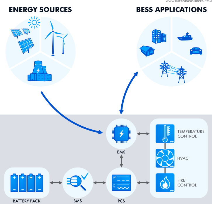
- Battery Energy Storage System (BESS):
- A BESS is a type of ESS that stores energy specifically in electrochemical batteries. It captures energy (from the grid or renewables), stores it, and releases it when needed.
- A BESS typically includes:
- batteries (e.g., lithium-ion)
- battery management system (BMS)
- power conversion system (inverter/rectifier)
- control and energy management system (EMS)
- “Battery energy storage system architecture” refers to the integration of these subsystems into a complete, controllable solution, not just the batteries themselves.
- Hybridized Energy Storage System (HESS):
- A Hybrid Energy Storage System (HESS) combines two or more storage technologies to leverage their complementary characteristics.
- This improves overall system performance, efficiency, and lifetime compared to a single technology.
- High-power components (e.g., supercapacitors) handle fast, short-duration peaks
- High-energy components (e.g., batteries) handle longer-duration energy supply
- Distributed Energy Storage Systems (DESS):
- Distributed Energy Storage Systems (DESS) are storage assets deployed across multiple locations in the grid rather than in a single centralized facility.
- These systems can range from residential batteries to utility-scale installations and are used to:
- store excess energy (e.g., from solar or wind)
- supply energy during peak demand
- improve grid stability and resilience
- DESS is a deployment model (where storage is located), not a specific technology.
- Switchgear (Core Concept):
- Broad term that describes a wide variety of switching devices that all fulfill a common need: controlling, protecting, and isolating electrical power systems.
It also includes devices for protection, switching, isolation, and in some cases measurement (metering), although metering is typically handled by dedicated instruments. - Switchgear contains fuses, switches, and other conductive and protective components. However, circuit breakers are typically the primary and most critical component in modern switchgear.
- It performs the function of controlling and protecting (not “metering” as a primary function) the flow of electrical power, as well as interrupting fault currents to prevent damage to equipment and ensure safety.
- There are three types of switchgear, namely:
- LV (Low Voltage)
- MV (Medium Voltage)
- HV (High Voltage)
- Broad term that describes a wide variety of switching devices that all fulfill a common need: controlling, protecting, and isolating electrical power systems.
- Fuses (Core Protection Devices):
- A fuse is a single-use overcurrent protection device that interrupts a circuit by melting a calibrated conductor when excessive current flows.
- Fuses are widely used from low voltage (LV) up to medium voltage (MV) and, more rarely, high voltage (HV) applications.
- It is an electrical safety device whose essential component is a metal wire or strip that melts when too much current flows, thereby interrupting the current.
- Circuit Breakers (Core Protection Devices):
- A circuit breaker is a mechanical electrical switch designed to protect an electrical circuit from damage caused by overcurrent, overload, or short circuit.
- Its basic function is to interrupt current flow automatically upon fault detection (either via internal thermal/magnetic mechanisms in LV systems or external protection relays in MV/HV systems).
- Unlike fuses, circuit breakers are resettable and reusable.
- Disconnectors (Core Protection Devices):
- A disconnector (also known as Isolator) is a mechanical switching device operated manually (or motorized) and only under no-load conditions to provide safe isolation.
- They are used to isolate equipment for maintenance and ensure visible and verifiable separation from live circuits (critical for safety procedures).
- Contactors (Core Protection Devices):
- A contactor is a remotely operated electrical switch used for frequent switching of circuits, especially motors.
- It is a special type of relay designed for higher current applications.
- Contactors cannot interrupt fault currents and therefore must always be used in combination with protective devices such as fuses or circuit breakers.
- Fuse Switch-Disconnectors (Hybrid – Combined Devices):
- A fuse switch-disconnector combines both protection and safe manual isolation in one device; it provides overcurrent protection like a fuse, and it also allows for manual disconnection of the circuit for isolation purposes.
- RCCB – Residual Current Circuit Breakers (Hybrid – Combined Devices):
- Protects against earth leakage (residual current) and electric shock.
- It does not protect against overload or short circuit and must therefore be used together with an MCB or fuse.
- RCD – Residual Current Devices (Hybrid – Combined Devices):
- General term for devices that disconnect circuits upon detecting leakage current.
- Trips typically within 10–50 ms, protecting against electrocution and fire.
- RCBO – Residual Current Breakers with Over-Current (Hybrid – Combined Devices):
- An RCBO protects against overcurrent + earth leakage in one device. It is a combination of:
- MCB (overcurrent protection)
- RCD (earth leakage protection)
- An RCBO protects against overcurrent + earth leakage in one device. It is a combination of:
- Circuit Breakers (By Application / Technology):
- MCB (Miniature Circuit Breakers):
- Used in domestic and light commercial installations.
- Rated current: typically up to 100–125 A
- Protects against overload and short circuit
- Widely replacing fuses in LV installations due to reset capability and ease of use
- Used in domestic and light commercial installations.
- MCCB (Molded Case Circuit Breakers):
- Used in industrial and commercial systems.
- Rated current: up to ~2500 A
- Higher breaking capacity than MCB
- Often includes adjustable trip settings for more precise protection
- Used in industrial and commercial systems.
- ACB (Air Circuit Breakers):
- Uses air as the arc insulating / quenching medium.
- Used in low voltage but high current applications (e.g., main incomers in buildings)
- VCB (Vacuum Circuit Breakers):
- Uses vacuum for arc quenching.
- Common in medium voltage systems
- OCB (Oil Circuit Breakers):
- Uses insulating oil for arc quenching.
- Now largely obsolete / being phased out due to fire risk, maintenance complexity, and environmental concerns
- Solid-State Circuit Breakers (also known as Semiconductor Circuit Breaker):
- Electronic devices using semiconductors to interrupt current extremely fast (microseconds).
- No moving parts
- Used in DC systems, data centers, EVs
- Key advantage: ultra-fast fault interruption compared to mechanical breakers
- Electronic devices using semiconductors to interrupt current extremely fast (microseconds).
- Hybrid Circuit Breakers:
- Combine mechanical + solid-state switching for:
- fast response
- low losses
- Combine mechanical + solid-state switching for:
- PTCB eFuse Circuit Breaker:
- An Electronic eFuse Circuit Breaker (PTCB) is an electronic micro fuse for DIN rail protecting very low currents (typically below 1A in control and electronics circuits) to facilitate clear fault detection and precise fault localization.
- Response times are shorter compared to conventional fuse protection and the exact current value can be adjusted at any time
- MCB (Miniature Circuit Breakers):
- Specialized Fuses:
- Reducer Fuses:
- A reducer fuse is not a fuse itself, but rather an adapter that allows a physically smaller fuse to be installed into a larger fuse holder. A fuse reducer typically consists of a non-conductive, insulating body that encases the smaller fuse.
- Electrified Vehicle (EV) Fuses:
- EV fuses are specialized safety devices designed to protect the high-voltage DC systems in electric vehicles.
- Specialized for:
- High-voltage DC (500–1000V+)
- High fault currents
- Harsh environments (temperature, vibration)
- Also designed to safely interrupt DC arcs, which are more difficult to extinguish than AC arcs
- Reducer Fuses:
- Switchgear Technologies:
- AIS (Air Insulated Switchgears):
- Uses air as insulation.
- Common in MV and HV outdoor substations due to simplicity and lower cost
- AIS controls, protects and isolates electrical equipment in power transmission and distribution systems.
- GIS (Gas Insulated Switchgears):
- Uses SF₆ gas (or alternatives) for insulation.
- It is a compact metal encapsulated switchgear consisting of high-voltage components such as circuit-breakers and disconnectors, which can be safely operated in space-constrained environments (e.g., cities).
- Pad-mount Switchgears:
- Outdoor, ground-mounted distribution switchgear used in utility and commercial networks
- The pad-mount switchgear is made from the same modular switch and interrupter components as the vault switchgear. This means all components are sealed, submersible and protected, so you don’t have to worry about tracking, animal infestation, corrosion or the effects of condensation inside the enclosure.
- Ring Main Unit (RMU):
- A ring Main Unit (RMU) is a Medium-Voltage, gas-insulated, fully sealed cabinet used to measure, connect, and integrate transformer protection functions with a fixed type breaker. Ring Main Units are safe, reliable, low-maintenance, and easy to replace switchgear.
- A Ring Main Unit (RMU) is a factory assembled, metal enclosed set of switchgear used at the load connection points of a ring-type distribution network.
- Dead Tank circuit Breaker (DTB):
- A Dead Tank Circuit Breaker (DTB) is a high-voltage, air-insulated switchgear where the interrupter units are housed in a grounded, metallic tank filled with insulating gas (typically SF6 or eco-friendly alternatives). It provides superior safety, seismic resistance, and allows for direct integration of current transformers, making it ideal for substation applications up to 800 kV.
- AIS (Air Insulated Switchgears):
- Distribution Systems:
- Load Center (Residential Distribution) – Panel Board (Commercial/industrial LV Distribution) – Switch Board (Large-scale industrial/commercial systems):
- A Load Center is used in residential and light commercial applications to distribute electricity supplied by the utility company throughout the home or building to feed all the branch circuits. Each branch circuit is protected by the circuit breaker housed in the load center.
- Panelboards are typically deeper and used in commercial/industrial LV systems, supporting more configurations.
- Panelboards are only accessible from the front while Switchboards allow rear access as well.
- Switchboards are used in large commercial and industrial systems and can handle higher currents and more complex distribution architectures.
- Distribution Box – Cabinets – Enclosures:
- General term for protective housings for electrical distribution components.
- Enclosures provide mechanical protection, electrical safety, and environmental isolation (dust, moisture, etc.)
- It can refer to enclosures containing Panelboards, Switchboards, or other distribution equipment.
- In terms of use, distribution boxes are generally used for households (smaller enclosures), and distribution cabinets are mostly used for centralized power supply. Distribution boxes and cabinets are complete sets of equipment. Distribution boxes are low-voltage complete sets of equipment. Cabinets have both high and low voltages.
- An enclosure or distribution enclosure in a general term for any type of protective housing for electrical distribution components. It’s essentially a cabinet or box designed to safeguard components from environmental factors, prevent electrical shock, and potentially shield against electromagnetic interference.
- Load Center (Residential Distribution) – Panel Board (Commercial/industrial LV Distribution) – Switch Board (Large-scale industrial/commercial systems):
- Distribution Hierachy:
- Main Distribution Boards (MDB):
- Primary distribution point receiving power from:
- Utility
- Transformer
- Generator
- An MDB is a panel or enclosure that houses the fuses, circuit breakers and ground leakage protection units where the electrical energy, which is used to distribute electrical power to numerous individual circuits or consumer points, is taken in from the transformer or an upstream panel.
- Primary distribution point receiving power from:
- Sub-Distribution Boards (SDB):
- Subsidiary from Main Distribution Board that distribute electricity to specific areas/zones of a building.
- A sub-distribution board or sub-board is usually a smaller breaker panel acting as a subsidiary to a larger Distribution Panel. This enables greater control and isolation of a subset of smaller circuits and breakers.
- Final Distribution Boards (FDB):
- Distribution Boards that received from the Sub-Distribution Boards and supply to the final switches that connect electrical devices and appliances.
- Main Distribution Boards (MDB):
- Meter Cabinet (Meter Box):
- This is the entry point for utility power into a building. It houses the electricity meter that measures power consumption and the main fuses belonging to the utility company.
- Typically sealed and controlled by the utility to prevent tampering with unmetered energy