
Schneider Electric – Solar and batteries could cut electricity costs by 40%, Schneider Electric research finds

New modeling shows total system electricity costs could fall by up to 40% – if installed solar and battery costs keep dropping and new electricity demand grows alongside them
Schneider Electric, a global energy technology leader, today published a report from the Schneider Electric Research Institute (SERI) examining how rising solar panel and battery adoption shapes total electricity costs.
The report, System Costs of Electricity: A new Baseline for the 21st Century Economy, modeled 40,500 scenarios across different combinations of solar, battery and grid costs to identify whether the rise of distributed energy resources (DERs) will ultimately raise or lower electricity costs overall.
It found that, when DER deployment is coordinated with electrification, the overall cost of running the electricity system could be cut by as much as 40% by the 2030s as solar panels and batteries scale up. These savings could translate into an additional 0.8% of GDP to the global economy by 2030.
Battery deployment was one of the most significant variables affecting total system costs. Under world-average cost conditions, a mismatch of battery durations across asset types can push total system costs to as much as 35% above the current benchmark.
The research found that the order in which solar, batteries and electrification are rolled out is just as important as how fast they scale. When deployment and demand growth move out of step — in either direction — total system costs can rise temporarily before falling. As renewables scale, it’s critical to accelerate new electrified demand such as EVs, heat pumps, data centers, alongside continued battery rollout. This new demand backfills the grid capacity freed up by batteries and flexibility, spreading fixed costs over more electricity sold and driving down the price per megawatt-hour. This helps to reduce spikes in grid demand and flatten the load curve, which frees up capacity for other users.
The report finds that individual households, businesses and industries making decisions in their own interest tend to land close to the lowest-cost outcome for the system as a whole – which benefits other consumers on the grid. Policy should focus on enabling adoption, not dictating how much solar or storage any individual site installs. The report sets out three priorities for making that happen:
- Flatten the load curve. Incentives such as time-of-use tariffs and demand charges, paired with combined solar-and-battery incentives, help new deployments reduce peak demand and free up existing grid capacity.
- Keep supply and demand moving together. Investment incentives that support solar and electrification side-by-side, and building codes that require new construction to account for both, help prevent the costly mismatches that arise when one scales faster than the other.
- Build the supply chain to bring costs down faster. Affordable components, public procurement, streamlined permitting, and training to address the shortage of skilled installers are what will accelerate the cost declines that the 40% savings depend on.
“For the past decade, solar has been experienced as an ‘intermittent’ energy source. But we’ve been looking at this generation asset in the wrong manner — solar is the fuel, the battery is the power plant,” said Laurent Bataille, executive vice president, Europe Operations, Schneider Electric. “Ultimately, batteries are making solar much more interesting. But the whole system only becomes cheaper if these work in harmony with one another. That also means building the electricity demand to use them, not just focusing on adding supply. By scaling solar and batteries far quicker, Europe can get on a path towards energy sovereignty and competitiveness. The pieces are falling into place – what we need now is acceleration and coordination.”
“This research shows that sustainability and affordability can reinforce each other, but coordination is critical. Now the priority must be to turn ambition into action by accelerating electrified demand, enabling more flexible energy use to flatten the load curve and free up capacity, and removing barriers to solar and battery deployment,” said Esther Finidori, chief sustainability officer, Schneider Electric.
SourceSchneider Electric
EMR Analysis
More information on Schneider Electric: See the full profile on EMR Executive Services
More information on Olivier Blum (Chief Executive Officer, Schneider Electric): See the full profile on EMR Executive Services
More information on Nathan Fast (Member of the Executive Committee and Executive Vice President, Group Chief Financial Officer, Schneider Electric): See the full profile on EMR Executive Services
More information on Laurent Bataille (Member of the Executive Committee and Executive Vice President, Europe Operations, Schneider Electric): See the full profile on EMR Executive Services
More information on the Schneider Electric Sustainability Strategy, Sustainability Impact 2030 Roadmap and 2025 Sustainability Report: See the full profile on EMR Executive Services
More information on Esther Finidori (Member of the Executive Committee and Chief Sustainability Officer, Schneider Electric): See the full profile on EMR Executive Services
More information on The Zero Carbon Pathway (TZCP) Program by Schneider Electric: https://www.se.com/ww/en/assets/564/document/234642/zero-carbon-project-schneider-electric.pdf + The Zero Carbon Pathway (TZCP)—originally launched in April 2021 as The Zero Carbon Project is Schneider Electric’s flagship supply chain decarbonization program designed to cut upstream greenhouse gas (GHG) emissions and reach a net-zero value chain by 2050
More information on the Schneider Electric Research Institute (SERI): https://www.se.com/ww/en/insights/sustainability/sustainability-research-institute/ + Electricity is the backbone of our modern economy. AI and digital infrastructure are connecting machines at scale. Power systems are becoming distributed and storable. Industry is being rebuilt around both. The Schneider Electric Research Institute (SERI) researches how fast this is happening, where it is stalling, and what it takes to get it right.
Reports, white papers, and articles on this page are produced independently or with academic and institutional partners. Peer-reviewed papers are published in external journals. SERI operates as an editorially independent institute within Schneider Electric.
SERI’s analysis is intended for policymakers, investors, and business leaders navigating decisions about where electrification is heading.
More information on “System Costs of Electricity Under High DER Penetration: A New Baseline for the 21st Century Economy” by the Schneider Electric Research Institute (SERI): https://www.se.com/ww/en/insights/sustainability/sustainability-research-institute/system-costs-electricity-new-baseline-21st-century-economy/ + The world faces today a tsunami of PV and battery (DERs) deployment. A question that arises as a result is whether this deployment will ultimately translate into higher or lower costs of electricity overall. The rationale behind this question has to do with the impact that this transition to DERs entails on the centralized electricity system, notably in terms of utilization. While individual adopters may enjoy early-on benefits from lower costs of electricity from DERs, they may also “free ride” the centralized system at the expense of others.
To answer this question, we develop a Total System Costs model which includes both DERs costs and centralized (utility) system costs. We explore 40,500 scenarios across different load profiles for individual assets and different system mix, with different DERs arrangements with different cost levels. We find that Total System Costs fall 10% below current levels at world’s average costs, a figure which could drop to 40% below current in the 2030s.
EMR Additional Notes:
- Grid, Microgrids, DERs and DERM’s:
- Grid / Power Grid:
- The power grid is a network for delivering electricity to consumers. The power grid includes power generation facilities, substations, transmission lines and towers, distribution networks, protection and control equipment, and associated communication and monitoring infrastructure.
- The grid continuously balances electricity generation and consumption while maintaining system stability and power quality, supplying electricity for applications ranging from industry to household appliances.
- Electric grids perform three major functions or stages of electricity supply: power generation, transmission, and distribution. Grid operation also includes functions such as system balancing, protection, control, monitoring, and, increasingly, energy storage and demand-side management.
- The power grid is a network for delivering electricity to consumers. The power grid includes power generation facilities, substations, transmission lines and towers, distribution networks, protection and control equipment, and associated communication and monitoring infrastructure.
- Microgrid:
- A microgrid is a group of interconnected loads and distributed energy resources (DERs) within clearly defined electrical boundaries that acts as a single controllable entity with respect to the main grid and can operate either connected to the main grid or, when appropriately designed, intentionally and controllably in an islanded mode.
- Microgrids can integrate local generation, energy storage, controllable loads, and other DERs to improve resilience, flexibility, efficiency, or local energy management.
- A microgrid is a group of interconnected loads and distributed energy resources (DERs) within clearly defined electrical boundaries that acts as a single controllable entity with respect to the main grid and can operate either connected to the main grid or, when appropriately designed, intentionally and controllably in an islanded mode.
- Smart Grid:
- A smart grid is an electrical grid enhanced with digital communications, sensing, automation, control, and data/analytics technologies across generation, transmission, distribution, and/or customer-side systems to improve the monitoring, operation, efficiency, reliability, resilience, and flexibility of the power system.
- Distributed Energy Resources (DERs):
- Distributed energy resources (DERs) are relatively small-scale electricity generation, storage, and flexible demand resources, located at or near the distribution system or customer premises, that can supply, store, or modify electricity consumption and are interconnected to the electric grid. They are often located close to load centers and can be used individually or in aggregate to provide value to the grid.
- Common examples of DERs include rooftop solar PV units, small wind turbines, small gas-fired generators or engines/turbines, microturbines, biomass generators, fuel cells, combined heat and power (CHP) or tri-generation systems with electrical generation, battery storage, electric vehicles and controllable EV charging or discharging where they can provide grid flexibility, and demand response applications.
- Distributed energy resources (DERs) are relatively small-scale electricity generation, storage, and flexible demand resources, located at or near the distribution system or customer premises, that can supply, store, or modify electricity consumption and are interconnected to the electric grid. They are often located close to load centers and can be used individually or in aggregate to provide value to the grid.
- Distributed Energy Resources Management Systems (DERMS):
- Distributed Energy Resources Management Systems (DERMS) are software platforms that help utilities, distribution system operators (DSOs), aggregators, and other energy-sector organizations monitor, provide visibility into, forecast, coordinate, optimize, and, where supported, control distributed energy resources (DERs).
- DERMS can be used to aggregate and coordinate large numbers of DERs and flexible loads for grid services, including voltage and power-flow management, congestion and constraint management, balancing, flexibility services, resilience, and participation in demand-response or other electricity markets. DERMS can be defined in many ways, depending on the use case, the types of DERs being managed, the responsibilities of the organization using the system, and the architecture of the power system.
- Distributed Energy Resources Management Systems (DERMS) are software platforms that help utilities, distribution system operators (DSOs), aggregators, and other energy-sector organizations monitor, provide visibility into, forecast, coordinate, optimize, and, where supported, control distributed energy resources (DERs).
- Grid / Power Grid:
- Energy Storage System (ESS):
- An Energy Storage System (ESS) is a system or group of components capable of storing energy in one form and delivering it later in the same or another usable form, including electrical energy.
- An ESS may include three main functional components:
- A Power Conversion System (PCS), which converts electrical power between different electrical forms, such as AC and DC, where required
- A storage unit, which stores the energy
- A control system, which manages energy flow, operating conditions, protection, and system operation
- ESS is a broad concept that includes multiple storage technologies (including electrochemical, mechanical, thermal, chemical, and electrical storage), not only electrical-to-electrical systems. Not every ESS necessarily contains a PCS or all of these components; the architecture depends on the storage technology and application.
- Battery Energy Storage System (BESS):
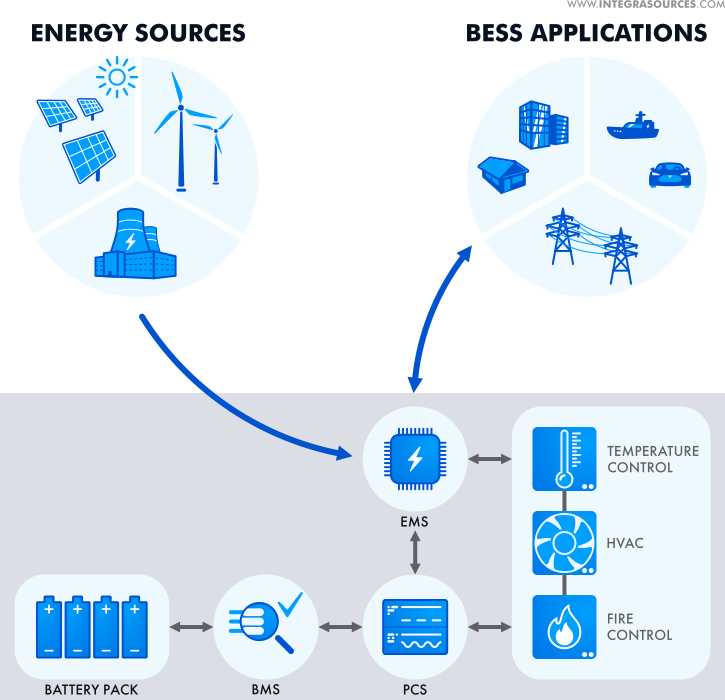
- A BESS is a type of ESS that stores energy specifically in rechargeable electrochemical batteries. It captures energy from sources such as the electrical grid or renewable generation, stores it, and releases it when needed.
- A BESS typically includes:
- battery cells assembled into modules, packs/racks, or other battery assemblies (e.g., lithium-ion)
- a Battery Management System (BMS)
- a bidirectional Power Conversion System (PCS), typically an inverter/rectifier for AC-grid applications
- an Energy Management System (EMS) and/or higher-level control system
- protection and, depending on the design, thermal-management, monitoring, switching, and auxiliary systems
- “Battery energy storage system architecture” refers to the structural and functional integration of these subsystems into a complete, controllable solution, not just the batteries themselves.
- Hybridized Energy Storage System (HESS):
- A Hybrid Energy Storage System (HESS) combines two or more different energy-storage technologies or storage subsystems to leverage their complementary characteristics.
- This can improve overall system performance, power/energy capability, efficiency, operating range, or lifetime when appropriately designed and controlled, compared to a single storage technology.
- High-power components (e.g., supercapacitors) handle rapid, short-duration power demands or peaks
- High-energy components (e.g., batteries) handle longer-duration energy storage and supply
- Distributed Energy Storage Systems (DESS):
- Distributed Energy Storage Systems (DESS) are energy-storage resources deployed across multiple geographically distributed locations rather than in a single centralized facility.
- These systems can range from residential batteries to commercial, industrial, community, and utility-scale installations and are used to:
- store excess energy (e.g., from solar or wind)
- supply energy during peak demand
- provide grid services such as flexibility, voltage support, frequency regulation, or congestion management, where applicable
- improve grid resilience and operational flexibility
- DESS is a deployment/distribution model (where storage is located), not a specific storage technology.
- GDP (Gross Domestic Product):
- GDP measures the monetary value of final goods and services—that is, those that are bought by the final user—produced in a country in a given period of time (say a quarter or a year). It counts all of the output generated within the borders of a country.
- Standard measure of the value added created through the production of goods and services in a country during a certain period. As such, it also measures the income earned from that production, or the total amount spent on final goods and services (less imports).
- GDP is defined by the following formula: GDP = Consumption + Investment + Government Spending + Net Exports or more succinctly as GDP = C + I + G + NX where consumption (C) represents private-consumption expenditures by households and nonprofit organizations, investment (I) refers to business expenditures by businesses and home purchases by households, government spending (G) denotes expenditures on goods and services by the government, and net exports (NX) represents a nation’s exports minus its imports.
- Heat Exchangers, Heat Pumps, Air Source Heat Pump (ASHP), Hydronics, Geothermal Heating – Cooling & Chillers:
- Heat Exchangers – Heat Transfer Foundation:
- Used to transfer heat from one medium to another. These media may be a gas, liquid, or a combination of both. The media may be separated by a solid wall to prevent mixing or may be in direct contact. Heat exchangers are required to provide heating and/or cooling to meet a process requirement.
- In HVAC, heat exchangers are used to transfer heat between the indoor and outdoor air streams while keeping them physically separated as a means of cooling or heating indoor air. heat exchangers are components; systems performing heating/cooling cycles are heat pumps, not the heat exchangers themselves.
- Gasketed heat exchangers are compact, highly efficient devices used to transfer heat between two fluids without mixing them. They consist of a series of corrugated metal plates fitted with elastomeric gaskets that seal the channels and direct the fluids into alternate pathways. This design creates high turbulence, maximizing heat transfer efficiency while maintaining a significantly smaller footprint than traditional shell-and-tube units.
- Heat Pumps – Thermodynamic Systems (Energy Transfer Devices):
- Use electricity to transfer heat from a cool space to a warm space, making the cool space cooler and the warm space warmer. During the heating season, heat pumps move heat from the cool outdoors into your warm house. During the cooling season, heat pumps move heat from your house into the outdoors. Because they transfer heat rather than generate heat, heat pumps can efficiently provide comfortable temperatures for your home. They operate on a vapor-compression refrigeration cycle (similar to air conditioners and chillers).
- Air Source Heat Pump (ASHP) – Thermodynamic Systems (Energy Transfer Devices):
- Heating and cooling system that extracts heat from the outside air and transfers it to a building’s interior for heating, or reverses the process to cool the building. ASHPs are a low-carbon alternative to traditional heating systems like gas boilers or oil furnaces. They are efficient because they transfer heat rather than generating it, typically providing a coefficient of performance (COP) of ~2–4 under typical conditions (can vary significantly with temperature).
- The only difference between a heat pump and a chiller is that one is designed to remove heat from a space or process stream, making it cooler and rejecting heat to the environment, while the other is designed to extract heat from the environment and use it to provide useful heat.
- Chillers – Cooling Systems (Heat Removal Focus):
- Mechanical systems that remove heat from a building’s liquid coolant, typically water, and transfer it to another location to cool the air and maintain comfort. Unlike traditional systems that might cool air directly, chillers generate chilled water that circulates through air handling units (AHUs) within the space to absorb heat, making them essential for cooling large commercial or industrial buildings.
- Chillers and heat pumps use similar thermodynamic cycles, but are designed and optimized for different applications (process/central cooling vs reversible heating/cooling).
- The only difference between a heat pump and a chiller is not strictly the function, but primarily the design intent and system integration:
- A chiller is typically designed to remove heat from a space or process (cooling-focused).
- A heat pump is designed to provide useful heating (and often reversible cooling).
- Hydronics – Distribution Systems (Energy Transport):
- Systems of heating or cooling that involves transfer of heat by a circulating fluid (such as water or vapor) in a closed system of pipes. Hydronic systems distribute thermal energy (heating or cooling) but do not generate it themselves.
- Geothermal Heating and Cooling Systems – Renewable / Ground-Based Systems:
- Take advantage of the relatively stable temperature underground using a piping system, commonly referred to as a “loop.” Water or a water-antifreeze mixture circulates in the loop to exchange heat between your home, the ground source heat pump, and the earth, providing geothermal heating, cooling, and hot water at very high efficiencies (often higher than ASHPs).
- Heat Exchangers – Heat Transfer Foundation:
- Fundamental Electrical Quantities and Units:
- Electric Current:
- Ampere (A): The ampere is the SI unit of electric current. Electric current represents the rate of flow of electric charge through a system. Depending on the medium, charge may be carried by electrons, ions, holes or other charge carriers.
- 1 A = 1 C/s
- In the current SI, the ampere is defined by fixing the elementary charge at exactly 1.602 176 634 × 10⁻¹⁹ C.
- Milliampere (mA): The milliampere is a unit of electric current equal to one-thousandth of an ampere.
- 1 mA = 10⁻³ A
- It is commonly used for small currents in electronic circuits, sensors, control systems and low-power devices.
- Kiloampere (kA): The kiloampere is a unit of electric current equal to 1,000 amperes.
- 1 kA = 10³ A
- It is commonly used to express high electrical currents, such as short-circuit currents, busbar ratings and current ratings of large electrical equipment.
- Ampere (A): The ampere is the SI unit of electric current. Electric current represents the rate of flow of electric charge through a system. Depending on the medium, charge may be carried by electrons, ions, holes or other charge carriers.
- Electrical Potential Difference (Voltage):
- Volt (V): The volt is the SI unit of electric potential difference, commonly called voltage. Voltage represents the difference in electric potential energy per unit electric charge between two points:
- 1 V = 1 J/C
- A potential difference can produce an electric current when an appropriate conductive path and circuit conditions exist.
- Kilovolt (kV): The kilovolt is a unit of electric potential difference equal to 1,000 volts:
- 1 kV = 10³ V
- Volt (V): The volt is the SI unit of electric potential difference, commonly called voltage. Voltage represents the difference in electric potential energy per unit electric charge between two points:
- Electrical Power and Energy:
- Power: Power is the rate at which energy is transferred, converted or delivered. The SI unit of power is the watt (W):
- 1 W = 1 J/s
- Electrical power may be expressed in W, kW, MW, GW or TW.
- Energy: Energy is the amount of energy transferred, converted or stored. Electrical energy is commonly expressed in joules (J) or watt-hours (Wh), including kWh, MWh and GWh.
- For constant power:
- Energy = Power × Time
- For variable power, energy is obtained by integrating power over time.
- Electrical energy consumption is commonly billed in kWh, although electricity tariffs may also include charges based on demand or capacity.
- Power: Power is the rate at which energy is transferred, converted or delivered. The SI unit of power is the watt (W):
- Real or Active Power:
- Real power (P), also called active power, is the average rate of net energy transfer in an electrical system. It represents the portion of electrical power associated with net transfer or conversion of energy, such as mechanical work, heat or light. It is expressed in watts (W) and its multiples.
- Kilowatt (kW): 1 kW = 1,000 W.
- Megawatt (MW): 1 MW = 1,000 kW = 1,000,000 W.
- Gigawatt (GW): 1 GW = 1,000 MW = 1,000,000,000 W.
- Terawatt (TW): 1 TW = 1,000 GW = 10¹² W. It is used for very large power levels, such as aggregated national or global generating capacity or instantaneous electrical demand. Energy consumed or generated over time should instead be expressed in units such as TWh.
- Apparent and Reactive Power:
- Apparent power (S) is a measure of the total RMS voltage-current loading of an AC system and is expressed in volt-amperes (VA). For sinusoidal AC:
- S = V × I
- Apparent power encompasses both active and reactive power. The apparent-power rating of equipment such as transformers, generators and UPS systems is commonly specified in VA, kVA or MVA.
- Kilovolt-ampere (kVA): 1 kVA = 1,000 VA.
- Megavolt-ampere (MVA): 1 MVA = 1,000 kVA = 1,000,000 VA.
- Reactive power (Q) is the component of AC power associated with the periodic exchange of energy between the electrical system and reactive elements such as inductors and capacitors. It is expressed in var (volt-amperes reactive), kVAr or MVAr.
- For sinusoidal AC: S² = P² + Q²
- and:
- P = S × power factor
- Thus, at a power factor below unity, apparent power is greater than active power.
- Apparent power (S) is a measure of the total RMS voltage-current loading of an AC system and is expressed in volt-amperes (VA). For sinusoidal AC:
- Specialized Renewable Energy Unit:
- Kilowatt-peak (kWp):
- kWp is a conventional designation for the rated peak power of a photovoltaic module or system under specified reference test conditions. It is a power rating, not a unit of energy. For conventional crystalline-silicon PV modules, Standard Test Conditions (STC) use an irradiance of 1,000 W/m², a cell temperature of 25°C and a specified reference solar spectrum.
- For example, four 270 W modules have a combined nominal peak rating of: 4 × 270 W = 1.08 kWp
- Actual electricity production depends on solar irradiance, orientation, tilt, shading, temperature, system losses, degradation and other operating conditions. Therefore, a kWp rating does not imply a fixed annual energy yield in kWh.
- Kilowatt-peak (kWp):
- Electric Current:
- Supply Chain:
- A supply chain is the end-to-end network of individuals, organizations, resources, activities, data, and technologies involved in the creation and delivery of a product or service—from raw materials to the final customer.
- A supply chain includes not only physical flows (goods), but also information flows and financial flows across all participants.
- At the most fundamental level, Supply Chain Management (SCM) is the integrated planning, coordination, and optimization of the flow of:
- goods
- information
- and finances
- from raw material sourcing to final delivery.
- At its core, SCM is not just “management of flows” but the optimization of those flows across cost, service level, speed, and risk.
- Supply Chain vs Logistics:
- Supply Chain: entire ecosystem (end-to-end)
- Logistics: subset focused on movement and storage of goods