ABB – ABB to supply control system for Japan’s first commercial-scale liquefied hydrogen terminal


- ABB selected by Kawasaki Heavy Industries, Ltd. to supply its ABB Ability™ System 800xA® distributed control system for the Kawasaki LH2 Terminal in Japan
- System 800xA will help operators manage complex hydrogen terminal operations safely, reliably and efficiently through one integrated platform
- Project builds on ABB’s work in the Hydrogen Energy Supply Chain (HESC) pilot, led by HySTRA, where ABB supplied the control and safety systems for the Hy touch Kobe liquefied hydrogen terminal
ABB has been selected by Kawasaki Heavy Industries, Ltd. to supply its ABB Ability™ System 800xA® distributed control system (DCS) for the Kawasaki LH2 Terminal in Ogishima, approximately 30 kilometers south of Tokyo, Japan – the world’s first facility designed to handle and scale liquefied hydrogen supply from pilot projects to commercial level1.
Expected to complete its demonstration phase by 2030, the terminal will play a central role in Japan’s ambition to build an international liquefied hydrogen supply chain. Supported by Japan Suiso Energy, Ltd. as project operator and the New Energy and Industrial Technology Development Organization (NEDO) under its Green Innovation Fund, this Liquefied Hydrogen Supply Chain Commercialization Demonstration project will include a 50,000 m³ liquefied hydrogen storage tank and facilities for cargo handling, liquefaction, hydrogen gas supply and lorry dispatch.
Once in operation, the facility is designed to receive, store and distribute imported liquefied hydrogen safely and at scale. ABB’s System 800xA will help achieve this by integrating process control, safety and operational data in one common environment, enabling faster decisions and greater operational visibility across the terminal.
ABB’s scope includes System 800xA integrated with a SIL 3 safety instrumented system (SIS), which will provide a unified platform for process control, safety and plant-wide operational visibility. The solution includes redundant AC 800M controllers and critical server infrastructure to support operations, data management and system availability, helping ensure reliable and continuous operation.
This integrated and redundant architecture reduces operational complexity, supports faster and more informed decision-making and improves availability across the terminal’s critical processes, from liquefaction and storage to loading, unloading and dispatch. This ensures stable and reliable performance in the event of equipment unavailability.
“Japan’s hydrogen ambitions depend on infrastructure that can operate safely, reliably and efficiently at commercial scale,” said Tetsuo Miura, Vice President of ABB’s Energy Industries division in Japan. “By bringing automation control, safety and operational insight together, we are proud to support the operations at Kawasaki LH2 Terminal as Japan takes an important step toward building a future-ready hydrogen supply chain.”
Liquefied hydrogen is an important option for transportation of hydrogen over long distances because it reduces the volume to approximately 1/800 compared to its gaseous state2. As Japan looks to establish an international hydrogen supply chain and transition to a low-carbon energy system3, reliable terminal operations will be essential to ensuring the supply chain is practical and scalable.
ABB’s role builds on its contribution to the Hydrogen Energy Supply Chain pilot4, where it supplied the control and safety systems for the Hy touch Kobe receiving terminal led by HySTRA. The Kawasaki LH2 Terminal extends that collaboration into commercial scale, supporting Kawasaki’s efforts to establish hydrogen as a viable energy carrier for Japan and global markets.
1 https://global.kawasaki.com/news_251127-2e.pdf
2 https://answers.khi.co.jp/en/energy-environment/20180131e-02/
3 https://www.meti.go.jp/shingikai/enecho/shoene_shinene/suiso_seisaku/pdf/20230606_5.pdf
4 https://www.hydrogenenergysupplychain.com/
SourceABB
EMR Analysis
More information on ABB: See full profile on EMR Executive Services
More information on Morten Wierod (Chief Executive Officer and Member of the Group Executive Committee, ABB): See full profile on EMR Executive Services
More information on Christian Nilsson (Chief Financial Officer and Member of the Executive Committee, ABB): See full profile on EMR Executive Services
More information on the ABB Way: See full profile on EMR Executive Services
More information on Automation Business Area by ABB: See the full profile on EMR Executive Services
More information on Peter Terwiesch (President, Automation Business Area and Member of the Executive Committee, ABB): See full profile on EMR Executive Services
More information on Tetsuo Miura (Vice President, Energy Industries Division, Japan, Automation Business Area, ABB): See full profile on EMR Executive Services
More information on ABB Ability™: See full profile on EMR Executive Services
More information on ABB Ability™ System 800xA® Distributed Control System by ABB: https://new.abb.com/control-systems/system-800xa + System 800xA is not only a DCS (Distributed Control System) it’s also an Electrical Control System, a Safety system and a collaboration enabler with the capacity to improve engineering efficiency, operator performance and asset utilization.
More information on AC 800M Controllers by ABB: https://new.abb.com/control-systems/system-800xa/800xa-dcs/hardware-controllers-io/ac800m-controllers + The AC 800M controllers is a family of rail-mounted modules, consisting of CPUs, communication modules, power supply modules and various accessories. Several CPU modules are available that vary in terms of processing power, memory size, SIL-rating, and redundancy support.
Each CPU module is equipped with two Ethernet ports for communication with other controllers and for interaction with operators, engineers, managers, and higher level applications. A Flash memory card can be inserted into a slot in the CPU module to store the application and data.
The connectivity and expansion options make the AC 800M exceptionally open and scalable, that is, easy to connect to the surrounding world of supervisory systems and intelligent devices of all kinds – and adaptable to changing requirements as the process it controls changes or expands.
More information on Kawasaki Heavy Industries, Ltd. by Kawasaki: https://global.kawasaki.com + Together with about 100 group companies in Japan and overseas, Kawasaki Heavy Industries oversees the formation of a “technology corporate group.” Our technological capabilities, polished over a history that exceeds a century, send diverse products forth into wide-ranging fields that go beyond land, sea, and air, extending from the ocean depths to space. Our aerospace division is active in products ranging from aircraft to satellites. The products that our rolling stock division delivers to the world include Shinkansen and New York subway cars, while our ship and offshore structure division’s products range from gas carriers and large tankers to submarines, and our energy solutions division covers the spectrum from development and manufacture of energy equipment to management systems. We are also active in wide-ranging businesses driven by diverse and high-level engineering technologies, including environmental and recycling plants, industrial plants, precision machinery, industrial robots, and infrastructure equipment. Finally, we operate our leisure and power products business that features the motorcycles known as the Kawasaki brand. Through the development of unique and broad businesses unmatched elsewhere, we will continue to create new values that solve the issues facing our customers and society.
More information on Yasuhiko Hashimoto (President and Chief Executive Officer, Kawasaki): https://global.kawasaki.com/en/corp/profile/executives/ + https://www.linkedin.com/in/yasuhiko-hashimoto-a8750bbb/
More information on The Hydrogen Energy Supply Chain (HESC) Pilot Project: https://www.hydrogenenergysupplychain.com/ + The Hydrogen Energy Supply Chain (HESC) Pilot Project was successfully completed in February 2022 with the arrival of the Suiso Frontier in Kobe, Japan with a load onboard of liquefied hydrogen extracted from Latrobe Valley coal.
HESC has been well supported by the Japanese, Australian, and Victorian Governments throughout the pilot phase.
The realisation of a hydrogen supply chain at commercial scale is being pursued by two consortia.
First is J-POWER and Sumitomo Corporation, to produce clean hydrogen from Latrobe Valley coal with carbon capture, utilisation and storage (CCUS).
The second is Japan Suiso Energy (JSE), comprised of Kawasaki Heavy Industries and Iwatani Corporation, responsible for liquefaction and trans-oceanic shipment to Japan.
More information on HySTRA: https://www.hystra.com/ + Hystra is a global consulting firm specialized in inclusive business. We support corporations, social businesses, impact investors and donors in designing sustainable and scalable strategies that change the lives of lower-income clients, suppliers or microdistributors across the globe.
Our main sectors of expertise include access to energy, agriculture, nutrition, healthcare and financial services, with last-mile distribution as a cross-cutting theme.
More information on Olivier Kayser (Founder and Senior Advisor, HySTRA): https://www.hystra.com/people + https://www.linkedin.com/in/olivier-kayser-88042/
More information on Japan Suiso Energy, Ltd.: https://www.japansuisoenergy.com/ + Japan Hydrogen Energy Co., Ltd., (JSE) was established in June 2021 with the primary purpose of conducting research, planning, operation, and investment related to the global supply chain of liquefied hydrogen.
Currently, in collaboration with Iwatani Corporation and ENEOS Corporation, we are working on a “demonstration of commercialization of a liquefied hydrogen supply chain” as part of the NEDO (New Energy and Industrial Technology Development Organization) Green Innovation Fund project, “Construction of a Large-Scale Hydrogen Supply Chain.”
As a pioneer in the global energy supply chain using liquefied hydrogen, JSE will actively work to shape the market through public-private partnerships and contribute to the realization of a sustainable decarbonized society.
More information on Eiichi Harada (Representative Director, Japan Suiso Energy, Ltd.): https://www.japansuisoenergy.com/
More information on New Energy and Industrial Technology Development Organization (NEDO): https://www.nedo.go.jp/english/ + The New Energy and Industrial Technology Development Organization (NEDO) is a national agency that supports technology development to address energy and global environmental problems and to enhance Japan’s industrial technology through commissioned projects and subsidies.
With approximately 1.4631 trillion yen in funding allocated in FY2024, NEDO is Japan’s largest incorporated administrative agency.
More information on Tamotsu Saito (Chairman, New Energy and Industrial Technology Development Organization (NEDO)): https://www.nedo.go.jp/english/introducing/introducing_message_c.html
EMR Additional Notes:
- Hydrogen:
- The atom of hydrogen is the first element in the periodic table, with chemical symbol H and hydrogen was one of the first elements formed in the early universe after the Big Bang. It is the most common element in the universe and the primary fuel for stars like the Sun (via nuclear fusion). It consists of one proton (positive charge) and one electron (negative charge) in its neutral atomic form.
- Hydrogen rarely exists in its pure form (H₂) on Earth. Molecular hydrogen (H₂) is relatively scarce naturally, because it readily forms covalent bonds, and most hydrogen is found in compounds such as:
- Water (H₂O)
- Hydrocarbons (e.g., methane CH₄, oil, and coal)
- Biomass (plants, organic matter)
- Hydrogen can be produced in numerous ways:
- Steam Methane Reforming (SMR) → produces a hydrogen-rich gas mixture and CO₂ as a by-product
- Electrolysis (using electricity) → can have very low lifecycle emissions if powered by low-carbon electricity, including renewable electricity
- Other methods (biomass, thermochemical, etc.)
- Hydrogen is a versatile energy carrier (not a primary energy source) that can be used for:
- Transportation (fuel cells, synthetic fuels)
- Industrial processes (e.g., ammonia, steel)
- Power generation and storage
- Heating (in specific applications)
- Hydrogen is a low-emission energy carrier at the point of use in a fuel cell, producing electricity, heat, and water rather than CO₂ when pure hydrogen is used as the fuel. It is particularly useful in sectors where electrification is difficult (heavy industry, long-distance transport). Its overall climate impact depends on how the hydrogen is produced, transported, stored, and used.
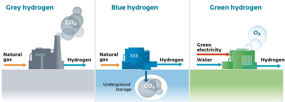
- Grey, Blue or Green Hydrogen:
- Where hydrogen comes from is critical:
- Grey Hydrogen: Produced from fossil fuels (mainly natural gas via SMR) → high CO₂ emissions
- Blue Hydrogen: Same as grey, but with Carbon Capture and Storage (CCS) to capture and permanently store a substantial portion of the CO₂ generated during production; residual and upstream emissions can remain
- Green Hydrogen: Produced via electrolysis using renewable electricity → potentially very low lifecycle greenhouse-gas emissions, depending on the electricity source and the full production system
- There is a growing consensus that hydrogen can play a key role in the energy transition, particularly for:
- Decarbonizing heavy industry
- Long-duration energy storage
- Heavy transport (shipping, aviation fuels, trucking) and other applications where direct electrification is technically difficult or inefficient
- Important: Grey, blue and green are commonly used industry colour classifications rather than universally standardized scientific categories. Other classifications include turquoise hydrogen (methane pyrolysis), pink hydrogen (nuclear-powered electrolysis), yellow hydrogen (electrolysis using grid electricity), and white hydrogen (naturally occurring geological hydrogen).
- Where hydrogen comes from is critical:
- Hydrogen Electrolyzer:
- An electrolyzer is a system that uses electricity to split water into hydrogen and oxygen in a process called electrolysis.
- At the cathode: water gains electrons → hydrogen gas (H₂) is produced
At the anode: water releases electrons → oxygen gas (O₂) is produced
- At the cathode: water gains electrons → hydrogen gas (H₂) is produced
- The cathode is the site of reduction and the anode is the site of oxidation. The exact electrode reactions depend on the electrolyzer technology, such as alkaline or proton-exchange membrane (PEM) electrolysis.
The overall reaction is: 2H₂O → 2H₂ + O₂. - The electrolyzer is therefore essentially the reverse electrochemical process of a fuel cell.
- An electrolyzer is a system that uses electricity to split water into hydrogen and oxygen in a process called electrolysis.
- Fuel Cell Plant:
- A fuel cell plant is a facility that generates electricity through an electrochemical reaction (not combustion).
- It works by combining:
- Hydrogen (fuel)
- Oxygen (from air)
- to produce:
- Electricity
- Heat
- Water
- Fuel cell systems:
- Produce very low emissions (no direct CO₂ emissions when pure hydrogen is used as the fuel; lifecycle emissions depend on hydrogen production and other upstream activities)
- Operate continuously as long as fuel is supplied
- Are used in power generation, backup systems, and mobility
- A fuel cell converts the chemical energy of hydrogen and an oxidant directly into electrical energy through electrochemical reactions, rather than first converting the fuel into heat through combustion.
- Distributed Control System (DCS):
- The distributed control system is designed to perform more complex and geographically larger industrial processes (typically continuous or process industries such as oil & gas, power, chemicals).
- The whole industrial process is divided into various control zones and is controlled by dedicated autonomous controllers (distributed control nodes). Field devices communicate with the controllers at the particular zone of control.
- These controllers are interconnected through a high-speed communication network and are connected to an engineering PC and operator workstations (HMI/SCADA layer) where overall control, monitoring, data logging, and alarming functions occur.
- In a distributed control system, automated control decisions are primarily made by the controllers themselves (closed-loop control at field level), with the plant operator providing oversight and intervening when necessary.
- DCS is a pre-engineered solution that requires configuration and logic development, rather than just programming like a PLC (with integrated libraries, standardized architectures, and system-wide engineering tools).
- Unlike standalone PLC systems, a DCS provides a fully integrated platform combining control, HMI, historian, and engineering tools within a unified architecture.
- Supply Chain:
- A supply chain is the end-to-end network of individuals, organizations, resources, activities, data, and technologies involved in the creation and delivery of a product or service—from raw materials to the final customer.
- A supply chain includes not only physical flows (goods), but also information flows and financial flows across all participants.
- At the most fundamental level, Supply Chain Management (SCM) is the integrated planning, coordination, and optimization of the flow of:
- goods
- information
- and finances
- from raw material sourcing to final delivery.
- At its core, SCM is not just “management of flows” but the optimization of those flows across cost, service level, speed, and risk.
- Supply Chain vs Logistics:
- Supply Chain: entire ecosystem (end-to-end)
- Logistics: subset focused on movement and storage of goods
- Safety Integrity Level (SIL):
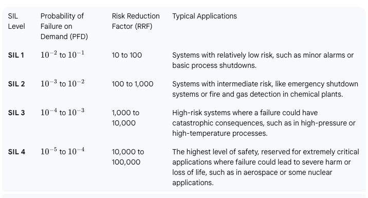
- SIL is a relative level of risk reduction provided by a safety function. SIL ratings correlate to the frequency and severity of hazards. They determine the performance required to maintain and achieve safety — and the probability of failure. There are four SILs — SIL 1, SIL 2, SIL 3, and SIL 4.
- The higher the SIL level, the higher the associated safety level, and the lower probability that a system will fail to perform properly.
- The International Electrotechnical Commission’s (IEC) standard IEC 61508 defines SIL
- There are four discrete SILs, from SIL 1 to SIL 4, each corresponding to a specific range of “Probability of Failure on Demand” (PFD) or “Probability of Dangerous Failure per hour” (PFH).
- Carbon Dioxide (CO2):
- The primary greenhouse gas emitted through human activities. Carbon dioxide enters the atmosphere through the burning of fossil fuels (coal, natural gas, and oil), solid waste, biomass (e.g. wood), and also as a result of certain industrial chemical reactions (e.g. cement production).
- Carbon dioxide is removed from the atmosphere (or “sequestered”) when it is absorbed by plants as part of the biological carbon cycle and through ocean absorption and geological processes. In climate accounting, however, “carbon sequestration” generally refers to the removal and storage of carbon in a reservoir; natural uptake through the carbon cycle is not necessarily classified as anthropogenic carbon dioxide removal (CDR).
- CO₂ is naturally part of the carbon cycle, but human activities have significantly increased its concentration in the atmosphere.
- Biogenic Carbon Dioxide (CO2):
- Biogenic CO₂ and fossil-derived CO₂ are chemically identical molecules.
- The distinction is not chemical, but source-based:
- Biogenic carbon: CO₂ released from organic materials such as plants, wood, soil, and biomass that were recently part of the natural carbon cycle. Its accounting treatment depends on the applicable carbon-accounting methodology and whether the carbon is considered part of the contemporary biogenic carbon cycle.
- Fossil carbon: CO₂ released from fossil fuels (coal, oil, gas), which were stored underground for millions of years. This introduces additional carbon into the active atmospheric carbon cycle and is therefore generally treated as fossil CO₂ emissions.
- CO2e (Carbon Dioxide Equivalent):
- CO₂e means “carbon dioxide equivalent”.
- It is a standardized climate metric used to express the total climate impact of multiple greenhouse gases in a single standardized unit.
- CO₂e converts all greenhouse gases (such as methane and nitrous oxide) into the amount of CO₂ that would have the same integrated radiative forcing / climate impact over a defined time period using a specified Global Warming Potential (GWP) value.
- Formula: CO₂e = mass of gas × Global Warming Potential (GWP)
- Carbon dioxide equivalents are commonly expressed as million metric tonnes of carbon dioxide equivalents, abbreviated as MtCO₂e or Mt CO₂-eq; “MMTCDE” is used in some datasets but is not the preferred general notation.
- The carbon dioxide equivalent for a gas is derived by multiplying the tonnes of the gas by the associated GWP: CO₂e = mass of gas × GWP.
- For example, the GWP for methane is approximately 27–30 under IPCC AR6 depending on the methane source and accounting convention, while the 100-year GWP for nitrous oxide is 273. This means that emissions of 1 million metric tonnes of methane and nitrous oxide respectively would correspond to approximately 27–30 and 273 million metric tonnes of CO₂e under those GWP assumptions.
- Carbon Footprint:
- There is no universally agreed definition of what a carbon footprint is.
- The most widely used definition (GHG Protocol) describes it as: “The total set of greenhouse gas (GHG) emissions caused directly and indirectly through an organization’s operations and value chain.” The GHG Protocol generally refers to corporate GHG inventories and Scope 1, 2 and 3 emissions rather than prescribing one universal definition of “carbon footprint.”
- A carbon footprint is the total amount of greenhouse gas (GHG) emissions caused directly and indirectly by an individual, organization, product, or activity.
- It is typically measured in CO₂e.
- Decarbonization:
- Reduction of carbon dioxide emissions through the use of low-carbon energy sources and improved efficiency, with the goal of reducing overall greenhouse gas emissions. More broadly, decarbonization refers to reducing the carbon intensity and/or absolute greenhouse-gas emissions of an economy, sector, organization, product, or process, potentially including CO₂ removal for residual emissions.
- Decarbonization typically refers to system-wide transition, not only emission reduction at a single source.
- Carbon Credits or Carbon Offsets:
- Carbon credits are tradable certificates representing the verified reduction or removal of one metric tonne of CO₂e, generally generated by a specific project or activity; terminology and quality criteria vary between carbon markets.
- They are part of cap-and-trade systems, where:
- A cap limits total emissions
- Companies receive or buy emission allowances
- Excess allowances can be traded
- Offsets are often linked to external projects that reduce or remove emissions (e.g. reforestation, renewable energy). A carbon offset is generally a credit representing a reduction or removal outside the entity’s own emissions boundary that may be used to compensate for emissions, subject to the applicable programme or claim rules.
- Carbon credits and emission allowances should not be treated as synonymous: an allowance is a regulated authorization to emit under a cap-and-trade system, whereas a credit/offset generally represents a quantified emission reduction or removal.
- Carbon Capture and Storage (CCS) – Carbon Capture, Utilisation and Storage (CCUS):
- CCS involves capturing CO₂ emissions from industrial processes or other concentrated sources and storing them permanently in geological formations (e.g. underground reservoirs).
- CCUS adds a utilization step, where captured CO₂ is reused as a feedstock (e.g. fuels, chemicals, building materials). More precisely, CCUS refers to carbon capture followed by utilization and/or storage; utilization does not necessarily result in permanent carbon storage.
- CCS = capture + geological storage; CCUS = capture + utilization and/or storage.
- Carbon Dioxide Removal (CDR) or Durable Carbon Removal:
- CDR refers to methods that actively remove CO₂ from the atmosphere and store it for long periods in geological, biological, or mineral form. CDR specifically requires an anthropogenic activity that removes atmospheric CO₂ and durably stores it in geological, terrestrial, ocean, or product reservoirs.
- Examples include:
- Direct Air Capture (DAC)
- Bioenergy with Carbon Capture (BECCS)
- Enhanced Rock Weathering (ERW)
- CDR creates net negative emissions when removal exceeds emissions. A CDR activity itself can provide a net removal only when the total emissions associated with the removal process are lower than the amount of CO₂ durably removed and stored.
- Direct Air Capture (DAC):
- Technologies that extract CO2 directly from the atmosphere at any location, unlike carbon capture which is generally carried out at the point of emissions, such as a steel plant. DAC can capture CO₂ from ambient air regardless of where the original emissions occurred; it is distinct from point-source carbon capture.
- Constraints like costs and energy requirements as well as the potential for pollution make DAC a less desirable option for CO2 reduction. Its larger land footprint when compared to other mitigation strategies like carbon capture and storage systems (CCS) also put it at a disadvantage. However, DAC is a potential carbon-removal technology rather than simply a CO₂-reduction technology, and its climate benefit depends strongly on the energy source, capture efficiency, permanence of storage, and lifecycle emissions.
- Direct Air Capture and Storage (DACCS):
- Climate technology that removes carbon dioxide (CO2) directly from the ambient atmosphere using large fans and chemical processes to bind with the CO2. The captured CO₂ is then transported and durably stored, typically in geological formations.
- DACCS is therefore a specific form of CDR: DAC + durable CO₂ storage.
- Bioenergy with Carbon Capture and Storage (BECCS):
- Technology that generates energy from biomass while capturing and storing the resulting CO₂.
- Because biomass absorbs CO₂ while growing, BECCS can result in net negative emissions. It can result in net negative emissions when the full lifecycle emissions—including biomass production, harvesting, transport, processing, energy use, and capture/storage—are sufficiently lower than the amount of biogenic CO₂ durably removed from the atmosphere.
- Enhanced Rock Weathering (ERW):
- Carbon dioxide removal (CDR) technique that accelerates the natural process of rock weathering by grinding silicate rocks into dust and spreading it on land, typically agricultural fields. This process enhances reactions with water and atmospheric CO₂, converting dissolved carbon into bicarbonate and, ultimately, carbonate minerals or transporting dissolved inorganic carbon to aquatic systems, where it can be stored over long timescales.
- Its effectiveness and permanence depend on rock type, particle size, weathering rates, transport pathways, soil and water chemistry, and the emissions associated with mining, grinding, and transporting the rock.
- Limits of Carbon Dioxide Storage:
- Carbon storage is not endless; the Earth’s capacity for permanently storing vast amounts of captured carbon, particularly in geological formations, is limited, potentially reaching a critical limit of 1,460 gigatonnes at around 2200, though storage durations vary significantly depending on the method, from decades for some biological methods to potentially millions of years for others like mineralization. Estimates of geological storage capacity vary widely and depend on geology, reservoir characteristics, storage efficiency, infrastructure, economics, regulation, monitoring, and permanence.
- While some methods offer very long-term storage, the sheer volume needed to meet climate targets requires scaling up storage significantly beyond current capacity, raising concerns about the available volume over time. The practical constraint is therefore better described as the need to develop sufficient safe, permanent, economically and technically accessible storage capacity rather than a single known global physical limit.
- Carbon Impregnation:
- Carbon impregnation is the process of treating activated carbon with chemical agents (such as metals, acids, or bases) to enhance its ability to adsorb specific, hard-to-remove pollutants. By loading substances like silver, sulfur, or potassium hydroxide into its pores, this material combines physical adsorption with chemical reaction for improved, targeted filtration in water and air. This is a materials engineering process, not a climate accounting concept.
- Global Warming:
- Global warming is the long-term heating of Earth’s climate system observed since the pre-industrial period (between 1850 and 1900) due to human activities, primarily fossil fuel burning, which increases heat-trapping greenhouse gas levels in Earth’s atmosphere. Global warming refers specifically to the long-term increase in Earth’s average surface temperature; climate change is the broader term encompassing associated changes in climate systems, including precipitation, extremes, sea level, and ecosystems.
- Global Warming Potential (GWP):
- A measure of how much heat a greenhouse gas contributes to climate warming relative to CO₂ over a specific time period (commonly 100 years).
- CO₂ has a GWP of 1.
- GWP is the scientific basis for converting gases into CO₂e.
- GWP was developed to allow comparisons of the global warming impacts of different gases. The numerical GWP depends on the selected IPCC assessment, time horizon, and, for some gases such as methane, the emission source and accounting convention.
- Greenhouse Gas (GHG):
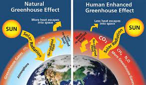
- Any gas that absorbs and emits infrared radiation in the atmosphere, contributing to the greenhouse effect.
- Main GHGs include:
- CO₂
- Methane (CH₄)
- Nitrous oxide (N₂O)
- Fluorinated gases such as HFCs, PFCs, SF₆ and NF₃
- Water vapor is a GHG but is not directly controlled by human emissions at scale. It is primarily a feedback in the climate system rather than a direct target of conventional anthropogenic GHG inventories.
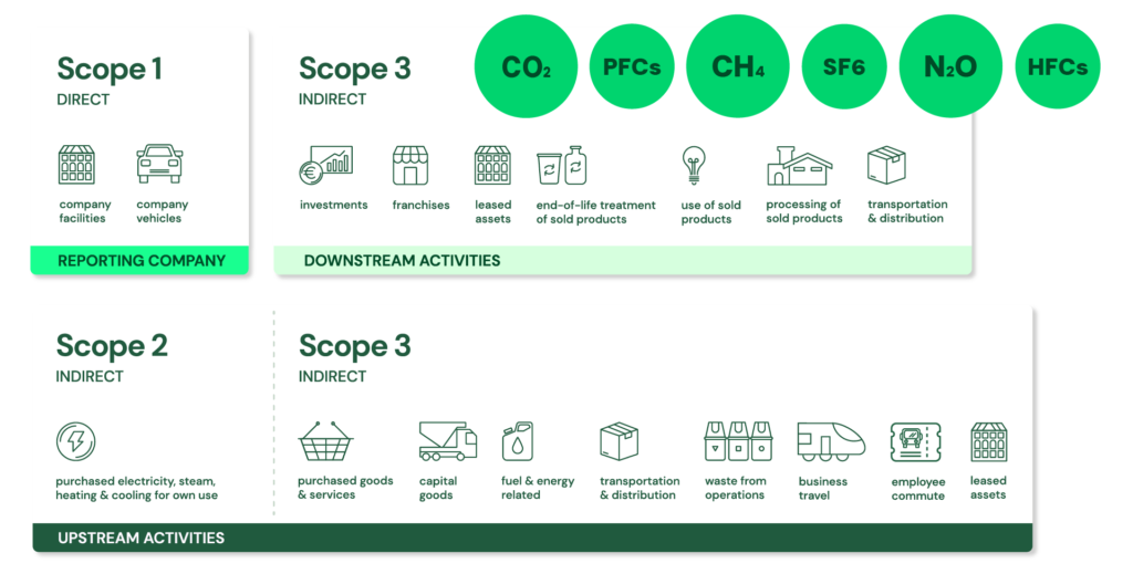
- GHG Protocol Corporate Standard Scope 1, 2 and 3: https://ghgprotocol.org/ + The GHG Protocol Corporate Accounting and Reporting Standard provides requirements and guidance for companies and other organizations preparing a corporate-level GHG emissions inventory. The Corporate Standard itself is voluntary, although companies may be required by applicable legislation or regulation to report using the GHG Protocol or equivalent requirements.
- Scope 1: Direct emissions:
- Direct emissions from company-owned and controlled resources. In other words, emissions are released into the atmosphere as a direct result of a set of activities, at a firm level. More precisely, Scope 1 covers direct GHG emissions from sources that are owned or controlled by the reporting organization.
- It is divided into four categories:
- Stationary combustion (e.g from fuels, heating sources). All fuels that produce GHG emissions must be included in scope 1. This applies when the combustion source is owned or controlled by the reporting organization.
- Mobile combustion is all vehicles owned or controlled by a firm, burning fuel (e.g. cars, vans, trucks). The increasing use of “electric” vehicles (EVs), means that some of the organisation’s fleets could fall into Scope 2 emissions. For example, fuel combustion in an owned/controlled vehicle is Scope 1, whereas electricity purchased to charge an EV is generally Scope 2; an EV itself does not create Scope 2 emissions—the purchased electricity does.
- Fugitive emissions are leaks from greenhouse gases (e.g. refrigeration, air conditioning units). It is important to note that refrigerant gases are not uniformly “a thousand times more dangerous” than CO₂; some refrigerants have GWPs of hundreds or thousands of times that of CO₂, while others have much lower values. Companies are encouraged to report these emissions.
- Process emissions are released during industrial processes, and on-site manufacturing (e.g. production of CO2 during cement manufacturing, factory fumes, chemicals). These are direct emissions resulting from physical or chemical processes other than fuel combustion, such as calcination in cement production..
- Scope 2: Indirect emissions – owned:
- Indirect emissions from the generation of purchased energy, from a utility provider. In other words, all GHG emissions released in the atmosphere, from the consumption of purchased electricity, steam, heat and cooling. Scope 2 covers indirect GHG emissions associated with the generation of purchased or acquired electricity, steam, heat, and cooling consumed by the reporting organization; “owned” is therefore misleading because the emissions source is owned or controlled by another entity.
- For most organisations, electricity will be the unique source of scope 2 emissions. Simply stated, the energy consumed falls into two scopes: Scope 2 covers the electricity consumed by the end-user. Scope 3 covers the energy used by the utilities during transmission and distribution (T&D) losses. More precisely, Scope 2 covers the generation-related emissions associated with purchased electricity, not the physical electricity itself. T&D losses are generally accounted for in Scope 3 Category 3 for an energy consumer that does not own the T&D system, although the treatment can vary depending on ownership and accounting circumstances.
- Scope 3: Indirect emissions – not owned:
- Indirect emissions – not included in scope 2 – that occur in the value chain of the reporting company, including both upstream and downstream emissions. In other words, emissions are linked to the company’s operations. According to the GHG protocol, scope 3 emissions are separated into 15 categories. Scope 3 therefore captures other indirect value-chain emissions, upstream and downstream, across the 15 defined categories of the Scope 3 Standard.
- Scope 1: Direct emissions: