Hitachi Energy – Hitachi Energy helps customers accelerate SF6-free grid modernization with new EconiQ wins
Strong global customer momentum demonstrates rising demand for SF₆-free technologies that modernize power grids without compromising reliability.
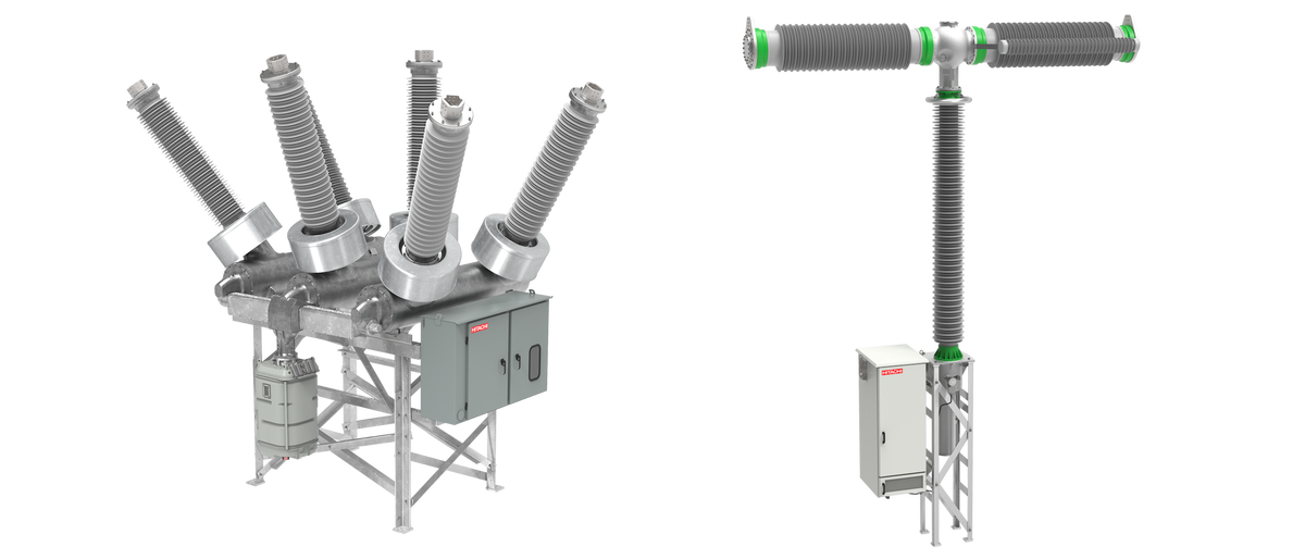
- Customer orders include the new EconiQ 245 kV dead tank circuit breaker from Hydro One Networks Inc. (Hydro One) and Wesco in North America, and the EconiQ 420 kV 80 kA live tank circuit breaker from TenneT Germany
- Unveiled at CIGRE in Paris, the expanded EconiQ portfolio helps utilities move away from SF6 while supporting grid modernization and decarbonization goals
Hitachi Energy, a global leader in electrification, today announced the launch of new additions in its EconiQ® high-voltage portfolio at CIGRE 2026 in Paris, reinforcing the company’s leadership in SF6-free technologies for the grid of the future.
As nations accelerate efforts to cut carbon emissions, replacing sulfur hexafluoride (SF6) in power grids is a crucial step toward more sustainable infrastructure. Hitachi Energy is supporting this transition with its latest solutions, including the EconiQ 300-kilovolt (kV) circuit breaker, available as a gas-insulated switchgear (GIS) or a 245 kV dead tank circuit breaker (DTB), and the EconiQ 420 kV 80 kiloamperes (kA) live tank circuit breaker (LTA).
SF6 remains the most widely used insulating and interrupting medium in high-voltage switchgear, prized for its performance but increasingly faulted for its negative climate impact. However, it is 24,300 times more potent than CO2 and can linger in the atmosphere for over a millennium. These SF6-based switchgear technologies are used in transmission and distribution networks worldwide, making them a critical part of resilient electricity systems. For utilities and corporations pursuing net-zero goals, eco-efficient technologies like Hitachi Energy’s EconiQ can help reduce the grid’s environmental footprint while maintaining the reliability customers depend on every day.
EconiQ is Hitachi Energy’s portfolio of SF6-free high-voltage switchgear that has pioneered several world-first innovations. With the introduction of new voltage levels, EconiQ’s footprint continues to expand, with more than 4,000 units ordered by customers in 40 different countries.
“Every SF6-free project helps customers reduce the long-term environmental impact of their grids while continuing to deliver the safe and reliable power their communities and industries need,” said Markus Heimbach, CEO of the High Voltage Products Business Unit at Hitachi Energy. “Switchgear is built to last for decades. The choices utilities make now about what goes into their substations will still be shaping grid emissions in 2060. That is exactly why we are expanding the EconiQ portfolio rating by rating, so customers have proven, SF6-free options at the voltage and performance levels they need today.”
Customer wins demonstrate growing demand for SF6-free grid technology
Both new EconiQ products have found enthusiastic acceptance from utilities seeking to stay ahead of evolving SF6 regulations and achieve their own sustainability commitments. It demonstrates that utilities and infrastructure partners are moving from ambition to action by deploying SF6-free technology in power grids.
In North America, Hydro One and Wesco have placed orders for the new EconiQ DTB 245 kV, highlighting the demand for sustainable grid solutions that can be deployed without compromising reliability or operational performance.
Hydro One, Ontario’s largest electricity transmission and distribution service provider, is investing in infrastructure and technologies that support a reliable, resilient and sustainable electricity system. The new EconiQ 245 kV circuit breakers will help modernize Hydro One’s transmission infrastructure while supporting efforts to reduce environmental impacts, strengthen grid resilience and prepare for future growth across the province.
“Ontario’s electricity demand is increasing, and continued investment in innovative, sustainable solutions is critical to maintaining a reliable and resilient grid,” said Lindsay Zylstra, Vice President, Supply Chain, Hydro One. “As we build and modernize Ontario’s electricity system to support growth, we will continue to work with trusted suppliers that invest in Canada and Ontario. Hitachi Energy’s continued expansion in the province helps strengthen our supply chain and ensures access to the equipment and technology needed to power Ontario’s future.”
Headquartered in Pittsburgh, Pennsylvania, Wesco is a FORTUNE 500™ company with approximately $24 billion in annual sales in 2025 and a leading provider of business-to-business distribution, logistics services, and supply chain solutions.
James Cameron, Executive Vice President and General Manager, Wesco Utility, said, “As the first purchaser of Hitachi’s 550 kV EconiQ Circuit Breaker, we fully support our customers’ need for infrastructure that performs as reliably as existing solutions, while helping them meet their sustainability goals. The new EconiQ DTB 245 kV switchgear checks both boxes.”
In Europe, transmission system operator TenneT Germany, following a successful EconiQ installation in Oberhaid, has ordered Hitachi Energy’s new EconiQ 420 kV 80 kA live tank circuit breaker. The solution supports TenneT Germany’s commitment to a lower-emission, highly reliable transmission network across Germany. Its higher fault-current rating gives the operator greater capacity to manage a grid carrying more renewable energy and cross-border power flows, while supporting the reliability of its more than 25,000 km network.
By adding 300 kV and a higher-current 420 kV rating to the EconiQ family, Hitachi Energy is giving customers more practical options to replace SF6 across a wider range of grid applications. The expanded portfolio helps close gaps where utilities have historically had no SF6-free alternatives, making it easier to align long-term grid investments with regulation, sustainability targets, and the energy transition.
SourceHitachi Energy
EMR Analysis
More information on Hitachi Ltd.: https://www.hitachi.com + Through its Social Innovation Business (SIB) that brings together IT, OT (Operational Technology) and products, Hitachi aims to be a global leader in continuously transforming social infrastructure through digital, contributing to a harmonized society where the environment, wellbeing, and economic growth are in balance. Hitachi operates worldwide across four sectors – Digital Systems & Services, Energy, Mobility, and Connective Industries – as well as a Strategic SIB Business Unit focused on new growth areas. With Lumada at its core, Hitachi creates value by combining data, technology and domain knowledge to solve customer and social challenges. Revenues for FY2025 (ended March 31, 2026) totaled 10,586.7 billion yen, with 606 consolidated subsidiaries and approximately 290,000 employees worldwide.
More information on Toshiaki Higashihara (Executive Chairman, Hitachi Ltd.): https://www.hitachi.com/corporate/about/officers/index.html#toshiaki-higashihara
More information on Toshiaki Tokunaga (President & Chief Executive Officer, Hitachi Ltd.): https://www.hitachi.com/New/cnews/month/2024/12/f_241216.pdf + https://www.linkedin.com/in/toshiaki-tokunaga-7113381aa/
More information on “Inspire 2027” Management Plan by Hitachi Ltd.: https://www.hitachi.com/content/dam/hitachi/global/en/press/files/2026/04/260427/f_260427pre.pdf + This strategic roadmap sets the course for our transformation into OneHitachi, with digital at its core, and highlights how we’ll transform ourselves into a digital-centric company.
The plan builds on key pillars such as evolving Lumada, leveraging AI and digital technologies, and strengthening regional strategies to capture new opportunities worldwide. It reflects our commitment to contribute to society through technology and address the challenges of a rapidly changing world with a long-term perspective.
More information on Hitachi Energy by Hitachi Ltd.: See the full profile on EMR Executive Services
More information on Andreas Schierenbeck (Senior Vice President and Executive Officer, Head of Energy Business, Hitachi, Ltd. + Chief Executive Officer, Hitachi Energy Ltd.): See the full profile on EMR Executive Services
More information on Ismo Haka (Chief Financial Officer and Executive Vice President, Hitachi Energy, Hitachi Energy Ltd.): See the full profile on EMR Executive Services
More information on High Voltage Products Business by Hitachi Energy: See the full profile on EMR Executive Services
More information on Dr. Markus Heimbach (Executive Vice President, Managing Director, High Voltage Products Business Unit, Hitachi Energy): See the full profile on EMR Executive Services
More information on EconiQ™ by Hitachi Energy: https://www.hitachienergy.com/ch/de/sustainability/econiq + EconiQ™ is Hitachi Energy’s eco-efficient portfolio for sustainability where products, services and solutions are proven to deliver exceptional environmental performance. EconiQ portfolio is sustainability-oriented in design to deliver a superior environmental performance compared to conventional solutions.
More information on Hydro One Networks Inc.: https://www.hydroone.com/ + Hydro One Limited, through its wholly-owned subsidiaries, is Ontario’s largest electricity transmission and distribution provider with 1.5 million valued customers, $39.7 billion in assets as at December 31, 2025, and annual revenues in 2025 of $9 billion.
Our team of 9,600 skilled and dedicated employees proudly build and maintain a safe and reliable electricity system which is essential to supporting strong and successful communities. In 2025, Hydro One invested $3.4 billion in its transmission and distribution networks, and supported the economy through buying $3.0 billion of goods and services.
We are committed to the communities where we live and work through community investment, sustainability and diversity initiatives.
Hydro One Limited’s common shares are listed on the TSX and certain of Hydro One Inc.’s medium term notes are listed on the NYSE.
More information on Megan Telford (President and Chief Executive Officer, Hydro One Networks Inc.): https://www.hydroone.com/about/corporate-information/senior-leadership-and-board + https://www.linkedin.com/in/megantelford/
More information on Lindsay Zylstra (Vice President, Supply Chain, Hydro One Networks Inc.): https://www.linkedin.com/in/lindsay-zylstra-ba2a6576/
More information on Wesco: See the full profile on EMR Executive Services
More information on Anixter by Wesco: See the full profile on EMR Executive Services
More information on John J. Engel (Chairman, President & Chief Executive Officer, Wesco): See the full profile on EMR Executive Services
More information on James F. Cameron (Executive Vice President, General Manager, Utility & Broadband Strategic Business Unit, Wesco): See the full profile on EMR Executive Services
More information on TenneT: https://www.tennet.eu + TenneT is a leading European grid operator. Committed to providing a secure and reliable supply of electricity 24 hours a day, 365 days a year, while helping to drive the energy transition in our pursuit of a brighter energy future – more sustainable, reliable and affordable than ever before. Lighting the way ahead together
Next time you turn on the lights, take a moment to think about where that power comes from. In the Netherlands and Germany, it was very likely brought to you by us, TenneT. We own and operate over 25,000 kilometres of high-voltage lines and cables.
As the Transmission System Operator (TSO) for the Netherlands, and a significant part of Germany, TenneT owns and operates over 25,000 kilometres of high-voltage lines and cables. We deliver electricity to 43 million domestic and business users, safely and reliably, 24 hours a day and 365 days a year. With over 7,400 employees in two countries, we are driven by our mission to ensure the lights stay on and that power is available, at the flick of a switch, whenever and wherever you need it.
To do this, we design, build, maintain and operate a high-voltage grid stretching across land and sea. This carries electricity from where it is made – including a rapidly increasing proportion of wind and solar energy – to where it is used. We carry it over ground, underground, under the sea and across borders, over our rapidly expanding high-voltage grid. With a service level as high as 99.99963 %, we are one of the best in the world at our job.
More information on Manon van Beek (Chairman of the Board and Chief Executive Officer, TenneT): https://www.tennet.eu/executive-board + https://www.linkedin.com/in/manonjjvanbeek/
More information on CIGRE: https://www.cigre.org/ + Established in 1921 in Paris, France, CIGRE is a non-profit global community committed to the collaborative sharing of power system expertise spanning distribution, transmission and generation.
The community features thousands of professionals from over 90 countries and includes some of the world’s leading experts. At its heart are CIGRE’s 60+ in-country National Committees, offering diverse technical perspectives and local expertise from every corner of the globe.
CIGRE operates the world’s preeminent knowledge development programme, spanning all aspects of the modern power system. The programme features 300+ Working Groups focusing on the key transmission and distribution topics the global power system faces today and in the future.
CIGRE’s knowledge programme includes an extensive range of local and international events, culminating every two years at the Paris Session in France, a unique thought-leadership congress and the number one global power system event.
CIGRE’s renowned publications, developed through the collaborative sharing of ‘real world experiences’, are in many cases the authoritative source of reference information.
All of this means that when electricity industry professionals look for the unbiased, fact-based answers they need, they turn to CIGRE, the world’s preeminent source for power system expertise.
CIGRE is a French acronym, standing for Conseil International des Grands Réseaux Electriques; this translates as Council on Large Electric Systems.
More information on Konstantin Papailiou (President, CIGRE): https://www.cigre.org/GB/about/governing-bodies + https://www.linkedin.com/in/konstantin-o-papailiou-433518294/?trk=public_post_main-feed-card-text
More information on CIGRE 2026 by CIGRE (August 23-28 – Paris, France): https://session.cigre.org/the-event/about-the-cigre-session.html + Every two years, CIGRE delivers the world’s foremost collaborative knowledge development and sharing programme for the power system sector. Through extensive remote collaboration and periodic face-to-face events, experts from around the globe contribute to advancing the industry. This unique programme culminates in the Paris Session – the leading international gathering for power system expertise.
Held in Paris in even-numbered years, the Session attracts around 9,000 participants from more than 100 countries, including over 3,600 international experts and decision-makers.
More information on Net Zero by 2050 by the United Nations: https://www.un.org/en/climatechange/net-zero-coalition + Put simply, net zero means cutting greenhouse gas emissions to as close to zero as possible, with any remaining emissions re-absorbed from the atmosphere, by oceans and forests for instance.
Currently, the Earth is already about 1.1°C warmer than it was in the late 1800s, and emissions continue to rise. To keep global warming to no more than 1.5°C – as called for in the Paris Agreement – emissions need to be reduced by 45% by 2030 and reach net zero by 2050.
More than 140 countries, including the biggest polluters – China, the United States, India and the European Union – have set a net-zero target, covering about 88% of global emissions. More than 9,000 companies, over 1000 cities, more than 1000 educational institutions, and over 600 financial institutions have joined the Race to Zero, pledging to take rigorous, immediate action to halve global emissions by 2030.
More information on Net Zero by 2050 by the Science Based Targets initiative (SBTi): https://sciencebasedtargets.org/net-zero + The SBTi’s Corporate Net-Zero Standard is the world’s only framework for corporate net-zero target setting in line with climate science. It includes the guidance, criteria, and recommendations companies need to set science-based net-zero targets consistent with limiting global temperature rise to 1.5°C.
UN vs. SBTi:
- UN targets nations, while SBTi focuses on companies. UN sets a broad goal, while SBTI provides a detailed framework for target setting.
- Both aim to achieve net zero emissions and limit warming to 1.5°C. The UN sets the overall direction, and SBTi helps businesses translate that goal into actionable plans.
Key components of the Corporate Net-Zero Standard:
- Near-term targets: Rapid, deep cuts to direct and indirect value-chain emissions must be the overarching priority for companies. Companies must set near-term science-based targets to roughly halve emission before 2030. This is the most effective, scientifically-sound way of limiting global temperature rise to 1.5°C.
- Long-term targets: Companies must set long-term science-based targets. Companies must cut all possible – usually more than 90% – of emissions before 2050.
- Neutralize residual emissions: After a company has achieved its long-term target and cut emissions by more than 90%, it must use permanent carbon removal and storage to counterbalance the final 10% or more of residual emissions that cannot be eliminated. A company is only considered to have reached net-zero when it has achieved its long-term science-based target and neutralized any residual emissions.
- Beyond Value Chain Mitigation (BVCM): Businesses should invest now in actions to reduce and remove emissions outside of their value chains in addition to near- and long-term science-based targets.
EMR Additional Notes:
- F-Gases:
- F stands for fluorinated, and F-gas is the term used to describe a particular family of fluorinated gases (synthetic, human-made gases containing fluorine) which are widely used as refrigerants in air conditioning and commercial refrigeration systems as well as in electrical equipment, fire protection systems, and medical applications.
- Fluorinated greenhouse gases (F-gases) are a family of gases containing fluorine. They are powerful greenhouse gases that trap heat in the atmosphere and contribute to global warming.
- They are often thousands of times more potent than CO₂ in terms of global warming potential (GWP) and their use is strictly regulated (e.g., under EU F-Gas Regulation and international climate frameworks).
- Main categories of F-gases include:
- HFCs (Hydrofluorocarbons): refrigeration / HVAC
- PFCs (Perfluorocarbons): industrial processes
- SF₆ (Sulfur hexafluoride): electrical insulation
- NF₃ (Nitrogen trifluoride): electronics manufacturing
- SF6:
- Sulfur hexafluoride (SF₆) is a synthetic fluorinated compound with an extremely stable molecular structure.
- Because of its unique dielectric properties, electric utilities rely heavily on SF₆ in electric power systems for:
- voltage insulation
- current interruption
- arc quenching
- (particularly in high-voltage switchgear such as Gas-Insulated Switchgear (GIS)) used in transmission and distribution networks.
- Yet, it is also the most potent greenhouse gas known to date in terms of GWP. Over a 100-year period, SF₆ is ~23,500 times more effective at trapping infrared radiation than CO₂.
- SF₆ is also a very stable chemical, with an atmospheric lifetime of ~3,200 years, meaning it accumulates in the atmosphere with virtually no natural degradation.
- Thus, even relatively small emissions can have a significant long-term impact on climate change.
- Global annual emissions are approximately 8,100 tonnes, which corresponds to very high CO₂-equivalent emissions due to its extreme GWP.
- It is expected to grow by ~75% by 2030 (driven by grid expansion and electrification).
- ~80% of all SF₆ is used in gas-insulated switchgear (GIS), making it a critical issue for the power transmission and distribution sector.
- Grid, Microgrids, DERs and DERM’s:
- Grid / Power Grid:
- The power grid is a network for delivering electricity to consumers. The power grid includes generator stations, transmission lines and towers, and distribution networks.
- The grid constantly balances the supply and demand for the energy that powers everything from industry to household appliances.
- Electric grids perform three major functions: generation, transmission, and distribution
- Microgrid:
- Small-scale power grid that can operate independently or collaboratively with other grids. The practice of using microgrids is known as distributed, dispersed, decentralized, district or embedded energy production.
- Group of interconnected loads and DERs (Distributed Energy Resources) within clearly defined electrical and geographical boundaries which acts as a single controllable entity with respect to the main grid.
- A microgrid can operate in both grid-connected mode and islanded (off-grid) mode.
- Smart Grid:
- An electrical grid enhanced with digital communication, automation, and IT systems across generation, transmission, distribution, and consumption levels.
- Enables real-time monitoring, control, demand response, and integration of DERs.
- Distributed Energy Resources (DERs):
- Small-scale electricity supply and demand-side resources (typically in the range of a few kW up to tens of MW, depending on definition) that are interconnected to the electric grid. They are power generation resources and are usually located close to load centers, and can be used individually or in aggregate to provide value to the grid.
- Common examples of DERs include rooftop solar PV units, natural gas turbines, microturbines, wind turbines, biomass generators, fuel cells, tri-generation units, battery storage, electric vehicles (EV) and EV chargers, and demand response resources (load flexibility).
- Distributed Energy Resources Management Systems (DERMS):
- Platforms which help mostly distribution system operators (DSO) manage their grids that are mainly based on distributed energy resources (DER).
- DERMS are used by utilities and other energy companies to aggregate and orchestrate distributed energy resources for participation in the demand response market and grid services (e.g., flexibility, voltage control, congestion management).
- Grid / Power Grid:
- Switchgear (Core Concept):
- Broad term that describes a wide variety of switching devices that all fulfill a common need: controlling, protecting, and isolating electrical power systems.
It also includes devices for protection, switching, isolation, and in some cases measurement (metering), although metering is typically handled by dedicated instruments. - Switchgear contains fuses, switches, and other conductive and protective components. However, circuit breakers are typically the primary and most critical component in modern switchgear.
- It performs the function of controlling and protecting (not “metering” as a primary function) the flow of electrical power, as well as interrupting fault currents to prevent damage to equipment and ensure safety.
- There are three types of switchgear, namely:
- LV (Low Voltage)
- MV (Medium Voltage)
- HV (High Voltage)
- Broad term that describes a wide variety of switching devices that all fulfill a common need: controlling, protecting, and isolating electrical power systems.
- Fuses (Core Protection Devices):
- A fuse is a single-use overcurrent protection device that interrupts a circuit by melting a calibrated conductor when excessive current flows.
- Fuses are widely used from low voltage (LV) up to medium voltage (MV) and, more rarely, high voltage (HV) applications.
- It is an electrical safety device whose essential component is a metal wire or strip that melts when too much current flows, thereby interrupting the current.
- Circuit Breakers (Core Protection Devices):
- A circuit breaker is a mechanical electrical switch designed to protect an electrical circuit from damage caused by overcurrent, overload, or short circuit.
- Its basic function is to interrupt current flow automatically upon fault detection (either via internal thermal/magnetic mechanisms in LV systems or external protection relays in MV/HV systems).
- Unlike fuses, circuit breakers are resettable and reusable.
- Disconnectors (Core Protection Devices):
- A disconnector (also known as Isolator) is a mechanical switching device operated manually (or motorized) and only under no-load conditions to provide safe isolation.
- They are used to isolate equipment for maintenance and ensure visible and verifiable separation from live circuits (critical for safety procedures).
- Contactors (Core Protection Devices):
- A contactor is a remotely operated electrical switch used for frequent switching of circuits, especially motors.
- It is a special type of relay designed for higher current applications.
- Contactors cannot interrupt fault currents and therefore must always be used in combination with protective devices such as fuses or circuit breakers.
- Fuse Switch-Disconnectors (Hybrid – Combined Devices):
- A fuse switch-disconnector combines both protection and safe manual isolation in one device; it provides overcurrent protection like a fuse, and it also allows for manual disconnection of the circuit for isolation purposes.
- RCCB – Residual Current Circuit Breakers (Hybrid – Combined Devices):
- Protects against earth leakage (residual current) and electric shock.
- It does not protect against overload or short circuit and must therefore be used together with an MCB or fuse.
- RCD – Residual Current Devices (Hybrid – Combined Devices):
- General term for devices that disconnect circuits upon detecting leakage current.
- Trips typically within 10–50 ms, protecting against electrocution and fire.
- RCBO – Residual Current Breakers with Over-Current (Hybrid – Combined Devices):
- An RCBO protects against overcurrent + earth leakage in one device. It is a combination of:
- MCB (overcurrent protection)
- RCD (earth leakage protection)
- An RCBO protects against overcurrent + earth leakage in one device. It is a combination of:
- Circuit Breakers (By Application / Technology):
- MCB (Miniature Circuit Breakers):
- Used in domestic and light commercial installations.
- Rated current: typically up to 100–125 A
- Protects against overload and short circuit
- Widely replacing fuses in LV installations due to reset capability and ease of use
- Used in domestic and light commercial installations.
- MCCB (Molded Case Circuit Breakers):
- Used in industrial and commercial systems.
- Rated current: up to ~2500 A
- Higher breaking capacity than MCB
- Often includes adjustable trip settings for more precise protection
- Used in industrial and commercial systems.
- ACB (Air Circuit Breakers):
- Uses air as the arc insulating / quenching medium.
- Used in low voltage but high current applications (e.g., main incomers in buildings)
- VCB (Vacuum Circuit Breakers):
- Uses vacuum for arc quenching.
- Common in medium voltage systems
- OCB (Oil Circuit Breakers):
- Uses insulating oil for arc quenching.
- Now largely obsolete / being phased out due to fire risk, maintenance complexity, and environmental concerns
- Solid-State Circuit Breakers (also known as Semiconductor Circuit Breaker):
- Electronic devices using semiconductors to interrupt current extremely fast (microseconds).
- No moving parts
- Used in DC systems, data centers, EVs
- Key advantage: ultra-fast fault interruption compared to mechanical breakers
- Electronic devices using semiconductors to interrupt current extremely fast (microseconds).
- Hybrid Circuit Breakers:
- Combine mechanical + solid-state switching for:
- fast response
- low losses
- Combine mechanical + solid-state switching for:
- PTCB eFuse Circuit Breaker:
- An Electronic eFuse Circuit Breaker (PTCB) is an electronic micro fuse for DIN rail protecting very low currents (typically below 1A in control and electronics circuits) to facilitate clear fault detection and precise fault localization.
- Response times are shorter compared to conventional fuse protection and the exact current value can be adjusted at any time
- MCB (Miniature Circuit Breakers):
- Specialized Fuses:
- Reducer Fuses:
- A reducer fuse is not a fuse itself, but rather an adapter that allows a physically smaller fuse to be installed into a larger fuse holder. A fuse reducer typically consists of a non-conductive, insulating body that encases the smaller fuse.
- Electrified Vehicle (EV) Fuses:
- EV fuses are specialized safety devices designed to protect the high-voltage DC systems in electric vehicles.
- Specialized for:
- High-voltage DC (500–1000V+)
- High fault currents
- Harsh environments (temperature, vibration)
- Also designed to safely interrupt DC arcs, which are more difficult to extinguish than AC arcs
- Reducer Fuses:
- Switchgear Technologies:
- AIS (Air Insulated Switchgears):
- Uses air as insulation.
- Common in MV and HV outdoor substations due to simplicity and lower cost
- AIS controls, protects and isolates electrical equipment in power transmission and distribution systems.
- GIS (Gas Insulated Switchgears):
- Uses SF₆ gas (or alternatives) for insulation.
- It is a compact metal encapsulated switchgear consisting of high-voltage components such as circuit-breakers and disconnectors, which can be safely operated in space-constrained environments (e.g., cities).
- Pad-Mount Switchgears:
- Outdoor, ground-mounted distribution switchgear used in utility and commercial networks
- The pad-mount switchgear is made from the same modular switch and interrupter components as the vault switchgear. This means all components are sealed, submersible and protected, so you don’t have to worry about tracking, animal infestation, corrosion or the effects of condensation inside the enclosure.
- Ring Main Unit (RMU):
- A ring Main Unit (RMU) is a Medium-Voltage, gas-insulated, fully sealed cabinet used to measure, connect, and integrate transformer protection functions with a fixed type breaker. Ring Main Units are safe, reliable, low-maintenance, and easy to replace switchgear.
- A Ring Main Unit (RMU) is a factory assembled, metal enclosed set of switchgear used at the load connection points of a ring-type distribution network.
- Dead Tank Circuit Breaker (DTB):
- A Dead Tank Circuit Breaker (DTB) is a high-voltage, air-insulated switchgear where the interrupter units are housed in a grounded, metallic tank filled with insulating gas (typically SF6 or eco-friendly alternatives). It provides superior safety, seismic resistance, and allows for direct integration of current transformers, making it ideal for substation applications up to 800 kV.
- AIS (Air Insulated Switchgears):
- Distribution Systems:
- Load Center (Residential Distribution) – Panel Board (Commercial/industrial LV Distribution) – Switch Board (Large-scale industrial/commercial systems):
- A Load Center is used in residential and light commercial applications to distribute electricity supplied by the utility company throughout the home or building to feed all the branch circuits. Each branch circuit is protected by the circuit breaker housed in the load center.
- Panelboards are typically deeper and used in commercial/industrial LV systems, supporting more configurations.
- Panelboards are only accessible from the front while Switchboards allow rear access as well.
- Switchboards are used in large commercial and industrial systems and can handle higher currents and more complex distribution architectures.
- Distribution Box – Cabinets – Enclosures:
- General term for protective housings for electrical distribution components.
- Enclosures provide mechanical protection, electrical safety, and environmental isolation (dust, moisture, etc.)
- It can refer to enclosures containing Panelboards, Switchboards, or other distribution equipment.
- In terms of use, distribution boxes are generally used for households (smaller enclosures), and distribution cabinets are mostly used for centralized power supply. Distribution boxes and cabinets are complete sets of equipment. Distribution boxes are low-voltage complete sets of equipment. Cabinets have both high and low voltages.
- An enclosure or distribution enclosure in a general term for any type of protective housing for electrical distribution components. It’s essentially a cabinet or box designed to safeguard components from environmental factors, prevent electrical shock, and potentially shield against electromagnetic interference.
- Load Center (Residential Distribution) – Panel Board (Commercial/industrial LV Distribution) – Switch Board (Large-scale industrial/commercial systems):
- Distribution Hierachy:
- Main Distribution Boards (MDB):
- Primary distribution point receiving power from:
- Utility
- Transformer
- Generator
- An MDB is a panel or enclosure that houses the fuses, circuit breakers and ground leakage protection units where the electrical energy, which is used to distribute electrical power to numerous individual circuits or consumer points, is taken in from the transformer or an upstream panel.
- Primary distribution point receiving power from:
- Sub-Distribution Boards (SDB):
- Subsidiary from Main Distribution Board that distribute electricity to specific areas/zones of a building.
- A sub-distribution board or sub-board is usually a smaller breaker panel acting as a subsidiary to a larger Distribution Panel. This enables greater control and isolation of a subset of smaller circuits and breakers.
- Final Distribution Boards (FDB):
- Distribution Boards that received from the Sub-Distribution Boards and supply to the final switches that connect electrical devices and appliances.
- Main Distribution Boards (MDB):
- Meter Cabinet (Meter Box):
- This is the entry point for utility power into a building. It houses the electricity meter that measures power consumption and the main fuses belonging to the utility company.
- Typically sealed and controlled by the utility to prevent tampering with unmetered energy
- Power Utility – Utilities:
- Also known as an electric utility or power company, a power utility is an organization (public or private) responsible for the generation, transmission, distribution, and sometimes retail supply (sale) of electricity to consumers. Depending on the electricity market structure, a power utility may perform one, several, or all of these functions.
- They often operate in regulated or partially liberalized markets, and are major providers of energy in most countries. Electricity transmission and distribution networks are generally regulated because they are natural monopolies, while generation and retail supply may be competitive in liberalized markets.
- Depending on the market structure, these functions may be vertically integrated (one company does everything) or unbundled across multiple entities (e.g., generation companies, transmission system operators, distribution network operators, retailers). In unbundled markets, these activities are separated among specialized organizations, although they remain interconnected within the overall electricity system.
- Utilities are critical infrastructure operators, ensuring reliability, grid stability, and continuous power supply to residential, commercial, and industrial users. However, responsibility for reliability and system operation may be divided among utilities, transmission and distribution system operators, and other electricity-sector organizations, and continuous supply cannot be guaranteed because outages and other disturbances can occur.
- Carbon Dioxide (CO2):
- The primary greenhouse gas emitted through human activities. Carbon dioxide enters the atmosphere through the burning of fossil fuels (coal, natural gas, and oil), solid waste, biomass (e.g. wood), and also as a result of certain industrial chemical reactions (e.g. cement production).
- Carbon dioxide is removed from the atmosphere (or “sequestered”) when it is absorbed by plants as part of the biological carbon cycle and through ocean absorption and geological processes. In climate accounting, however, “carbon sequestration” generally refers to the removal and storage of carbon in a reservoir; natural uptake through the carbon cycle is not necessarily classified as anthropogenic carbon dioxide removal (CDR).
- CO₂ is naturally part of the carbon cycle, but human activities have significantly increased its concentration in the atmosphere.
- Biogenic Carbon Dioxide (CO2):
- Biogenic CO₂ and fossil-derived CO₂ are chemically identical molecules.
- The distinction is not chemical, but source-based:
- Biogenic carbon: CO₂ released from organic materials such as plants, wood, soil, and biomass that were recently part of the natural carbon cycle. Its accounting treatment depends on the applicable carbon-accounting methodology and whether the carbon is considered part of the contemporary biogenic carbon cycle.
- Fossil carbon: CO₂ released from fossil fuels (coal, oil, gas), which were stored underground for millions of years. This introduces additional carbon into the active atmospheric carbon cycle and is therefore generally treated as fossil CO₂ emissions.
- CO2e (Carbon Dioxide Equivalent):
- CO₂e means “carbon dioxide equivalent”.
- It is a standardized climate metric used to express the total climate impact of multiple greenhouse gases in a single standardized unit.
- CO₂e converts all greenhouse gases (such as methane and nitrous oxide) into the amount of CO₂ that would have the same integrated radiative forcing / climate impact over a defined time period using a specified Global Warming Potential (GWP) value.
- Formula: CO₂e = mass of gas × Global Warming Potential (GWP)
- Carbon dioxide equivalents are commonly expressed as million metric tonnes of carbon dioxide equivalents, abbreviated as MtCO₂e or Mt CO₂-eq; “MMTCDE” is used in some datasets but is not the preferred general notation.
- The carbon dioxide equivalent for a gas is derived by multiplying the tonnes of the gas by the associated GWP: CO₂e = mass of gas × GWP.
- For example, the GWP for methane is approximately 27–30 under IPCC AR6 depending on the methane source and accounting convention, while the 100-year GWP for nitrous oxide is 273. This means that emissions of 1 million metric tonnes of methane and nitrous oxide respectively would correspond to approximately 27–30 and 273 million metric tonnes of CO₂e under those GWP assumptions.
- Carbon Footprint:
- There is no universally agreed definition of what a carbon footprint is.
- The most widely used definition (GHG Protocol) describes it as: “The total set of greenhouse gas (GHG) emissions caused directly and indirectly through an organization’s operations and value chain.” The GHG Protocol generally refers to corporate GHG inventories and Scope 1, 2 and 3 emissions rather than prescribing one universal definition of “carbon footprint.”
- A carbon footprint is the total amount of greenhouse gas (GHG) emissions caused directly and indirectly by an individual, organization, product, or activity.
- It is typically measured in CO₂e.
- Decarbonization:
- Reduction of carbon dioxide emissions through the use of low-carbon energy sources and improved efficiency, with the goal of reducing overall greenhouse gas emissions. More broadly, decarbonization refers to reducing the carbon intensity and/or absolute greenhouse-gas emissions of an economy, sector, organization, product, or process, potentially including CO₂ removal for residual emissions.
- Decarbonization typically refers to system-wide transition, not only emission reduction at a single source.
- Carbon Credits or Carbon Offsets:
- Carbon credits are tradable certificates representing the verified reduction or removal of one metric tonne of CO₂e, generally generated by a specific project or activity; terminology and quality criteria vary between carbon markets.
- They are part of cap-and-trade systems, where:
- A cap limits total emissions
- Companies receive or buy emission allowances
- Excess allowances can be traded
- Offsets are often linked to external projects that reduce or remove emissions (e.g. reforestation, renewable energy). A carbon offset is generally a credit representing a reduction or removal outside the entity’s own emissions boundary that may be used to compensate for emissions, subject to the applicable programme or claim rules.
- Carbon credits and emission allowances should not be treated as synonymous: an allowance is a regulated authorization to emit under a cap-and-trade system, whereas a credit/offset generally represents a quantified emission reduction or removal.
- Carbon Capture and Storage (CCS) – Carbon Capture, Utilisation and Storage (CCUS):
- CCS involves capturing CO₂ emissions from industrial processes or other concentrated sources and storing them permanently in geological formations (e.g. underground reservoirs).
- CCUS adds a utilization step, where captured CO₂ is reused as a feedstock (e.g. fuels, chemicals, building materials). More precisely, CCUS refers to carbon capture followed by utilization and/or storage; utilization does not necessarily result in permanent carbon storage.
- CCS = capture + geological storage; CCUS = capture + utilization and/or storage.
- Carbon Dioxide Removal (CDR) or Durable Carbon Removal:
- CDR refers to methods that actively remove CO₂ from the atmosphere and store it for long periods in geological, biological, or mineral form. CDR specifically requires an anthropogenic activity that removes atmospheric CO₂ and durably stores it in geological, terrestrial, ocean, or product reservoirs.
- Examples include:
- Direct Air Capture (DAC)
- Bioenergy with Carbon Capture (BECCS)
- Enhanced Rock Weathering (ERW)
- CDR creates net negative emissions when removal exceeds emissions. A CDR activity itself can provide a net removal only when the total emissions associated with the removal process are lower than the amount of CO₂ durably removed and stored.
- Direct Air Capture (DAC):
- Technologies that extract CO2 directly from the atmosphere at any location, unlike carbon capture which is generally carried out at the point of emissions, such as a steel plant. DAC can capture CO₂ from ambient air regardless of where the original emissions occurred; it is distinct from point-source carbon capture.
- Constraints like costs and energy requirements as well as the potential for pollution make DAC a less desirable option for CO2 reduction. Its larger land footprint when compared to other mitigation strategies like carbon capture and storage systems (CCS) also put it at a disadvantage. However, DAC is a potential carbon-removal technology rather than simply a CO₂-reduction technology, and its climate benefit depends strongly on the energy source, capture efficiency, permanence of storage, and lifecycle emissions.
- Direct Air Capture and Storage (DACCS):
- Climate technology that removes carbon dioxide (CO2) directly from the ambient atmosphere using large fans and chemical processes to bind with the CO2. The captured CO₂ is then transported and durably stored, typically in geological formations.
- DACCS is therefore a specific form of CDR: DAC + durable CO₂ storage.
- Bioenergy with Carbon Capture and Storage (BECCS):
- Technology that generates energy from biomass while capturing and storing the resulting CO₂.
- Because biomass absorbs CO₂ while growing, BECCS can result in net negative emissions. It can result in net negative emissions when the full lifecycle emissions—including biomass production, harvesting, transport, processing, energy use, and capture/storage—are sufficiently lower than the amount of biogenic CO₂ durably removed from the atmosphere.
- Enhanced Rock Weathering (ERW):
- Carbon dioxide removal (CDR) technique that accelerates the natural process of rock weathering by grinding silicate rocks into dust and spreading it on land, typically agricultural fields. This process enhances reactions with water and atmospheric CO₂, converting dissolved carbon into bicarbonate and, ultimately, carbonate minerals or transporting dissolved inorganic carbon to aquatic systems, where it can be stored over long timescales.
- Its effectiveness and permanence depend on rock type, particle size, weathering rates, transport pathways, soil and water chemistry, and the emissions associated with mining, grinding, and transporting the rock.
- Limits of Carbon Dioxide Storage:
- Carbon storage is not endless; the Earth’s capacity for permanently storing vast amounts of captured carbon, particularly in geological formations, is limited, potentially reaching a critical limit of 1,460 gigatonnes at around 2200, though storage durations vary significantly depending on the method, from decades for some biological methods to potentially millions of years for others like mineralization. Estimates of geological storage capacity vary widely and depend on geology, reservoir characteristics, storage efficiency, infrastructure, economics, regulation, monitoring, and permanence.
- While some methods offer very long-term storage, the sheer volume needed to meet climate targets requires scaling up storage significantly beyond current capacity, raising concerns about the available volume over time. The practical constraint is therefore better described as the need to develop sufficient safe, permanent, economically and technically accessible storage capacity rather than a single known global physical limit.
- Carbon Impregnation:
- Carbon impregnation is the process of treating activated carbon with chemical agents (such as metals, acids, or bases) to enhance its ability to adsorb specific, hard-to-remove pollutants. By loading substances like silver, sulfur, or potassium hydroxide into its pores, this material combines physical adsorption with chemical reaction for improved, targeted filtration in water and air. This is a materials engineering process, not a climate accounting concept.
- Global Warming:
- Global warming is the long-term heating of Earth’s climate system observed since the pre-industrial period (between 1850 and 1900) due to human activities, primarily fossil fuel burning, which increases heat-trapping greenhouse gas levels in Earth’s atmosphere. Global warming refers specifically to the long-term increase in Earth’s average surface temperature; climate change is the broader term encompassing associated changes in climate systems, including precipitation, extremes, sea level, and ecosystems.
- Global Warming Potential (GWP):
- A measure of how much heat a greenhouse gas contributes to climate warming relative to CO₂ over a specific time period (commonly 100 years).
- CO₂ has a GWP of 1.
- GWP is the scientific basis for converting gases into CO₂e.
- GWP was developed to allow comparisons of the global warming impacts of different gases. The numerical GWP depends on the selected IPCC assessment, time horizon, and, for some gases such as methane, the emission source and accounting convention.
- Greenhouse Gas (GHG):
- Any gas that absorbs and emits infrared radiation in the atmosphere, contributing to the greenhouse effect.
- Main GHGs include:
- CO₂
- Methane (CH₄)
- Nitrous oxide (N₂O)
- Fluorinated gases such as HFCs, PFCs, SF₆ and NF₃
- Water vapor is a GHG but is not directly controlled by human emissions at scale. It is primarily a feedback in the climate system rather than a direct target of conventional anthropogenic GHG inventories.
- GHG Protocol Corporate Standard Scope 1, 2 and 3: https://ghgprotocol.org/ + The GHG Protocol Corporate Accounting and Reporting Standard provides requirements and guidance for companies and other organizations preparing a corporate-level GHG emissions inventory. The Corporate Standard itself is voluntary, although companies may be required by applicable legislation or regulation to report using the GHG Protocol or equivalent requirements.
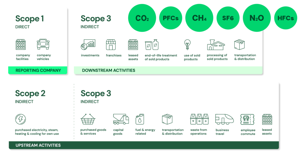
- Scope 1: Direct emissions:
- Direct emissions from company-owned and controlled resources. In other words, emissions are released into the atmosphere as a direct result of a set of activities, at a firm level. More precisely, Scope 1 covers direct GHG emissions from sources that are owned or controlled by the reporting organization.
- It is divided into four categories:
- Stationary combustion (e.g from fuels, heating sources). All fuels that produce GHG emissions must be included in scope 1. This applies when the combustion source is owned or controlled by the reporting organization.
- Mobile combustion is all vehicles owned or controlled by a firm, burning fuel (e.g. cars, vans, trucks). The increasing use of “electric” vehicles (EVs), means that some of the organisation’s fleets could fall into Scope 2 emissions. For example, fuel combustion in an owned/controlled vehicle is Scope 1, whereas electricity purchased to charge an EV is generally Scope 2; an EV itself does not create Scope 2 emissions—the purchased electricity does.
- Fugitive emissions are leaks from greenhouse gases (e.g. refrigeration, air conditioning units). It is important to note that refrigerant gases are not uniformly “a thousand times more dangerous” than CO₂; some refrigerants have GWPs of hundreds or thousands of times that of CO₂, while others have much lower values. Companies are encouraged to report these emissions.
- Process emissions are released during industrial processes, and on-site manufacturing (e.g. production of CO2 during cement manufacturing, factory fumes, chemicals). These are direct emissions resulting from physical or chemical processes other than fuel combustion, such as calcination in cement production..
- Scope 2: Indirect emissions – owned:
- Indirect emissions from the generation of purchased energy, from a utility provider. In other words, all GHG emissions released in the atmosphere, from the consumption of purchased electricity, steam, heat and cooling. Scope 2 covers indirect GHG emissions associated with the generation of purchased or acquired electricity, steam, heat, and cooling consumed by the reporting organization; “owned” is therefore misleading because the emissions source is owned or controlled by another entity.
- For most organisations, electricity will be the unique source of scope 2 emissions. Simply stated, the energy consumed falls into two scopes: Scope 2 covers the electricity consumed by the end-user. Scope 3 covers the energy used by the utilities during transmission and distribution (T&D) losses. More precisely, Scope 2 covers the generation-related emissions associated with purchased electricity, not the physical electricity itself. T&D losses are generally accounted for in Scope 3 Category 3 for an energy consumer that does not own the T&D system, although the treatment can vary depending on ownership and accounting circumstances.
- Scope 3: Indirect emissions – not owned:
- Indirect emissions – not included in scope 2 – that occur in the value chain of the reporting company, including both upstream and downstream emissions. In other words, emissions are linked to the company’s operations. According to the GHG protocol, scope 3 emissions are separated into 15 categories. Scope 3 therefore captures other indirect value-chain emissions, upstream and downstream, across the 15 defined categories of the Scope 3 Standard.
- Scope 1: Direct emissions:
- Extra Low-Voltage (ELV):
- Extra-Low Voltage (ELV) is defined as a voltage of ≤ 50 V AC (RMS) or ≤ 120 V DC (ripple-free).
- ELV systems are typically used where electrical safety is critical (e.g., building automation, control circuits, lighting, telecom).
- Low-Voltage (LV):
- The International Electrotechnical Commission (IEC) defines Low Voltage (LV) for supply systems as voltage in the range > 50–1000 V AC or > 120–1500 V DC.
- Medium-Voltage (MV):
- Medium Voltage (MV) is a voltage class that typically falls between low voltage and high voltage, with a common range being from > 1 kV up to ~30–36 kV (typical IEC practice).
- Some regions (e.g., North America) extend MV up to ~69 kV, depending on utility definitions.
- High-Voltage (HV):
- The International Electrotechnical Commission defines high voltage as above 1000 V AC and above 1500 V DC.
- In practice, HV is often considered from ~36 kV up to ~230 kV in transmission systems.
- Super High-Voltage or Extra High-Voltage (EHV):
- Extra High-Voltage (EHV) is the voltage class used for long-distance bulk power transmission. The range for EHV systems is typically from ~220 kV to ~765–800 kV. “Super High Voltage” is not a standard IEC term.
- Ultra High-Voltage (UHV):
- Ultra High-Voltage (UHV) is the highest voltage class used in electrical transmission, defined as a voltage of ≥ 800 kV (AC) and ≥ 800–1000 kV (DC, depending on classification).
- Substation:
- A power station is where the power is generated. A substation is a critical part of an electrical transmission and distribution system (not generation itself), where power is transformed, switched, controlled, and distributed further into the grid.
- Substations contain specialized equipment that allows the voltage of electricity to be transformed and controlled. The voltage is stepped up or down through transformers located within the substation.
- Substations also perform protection, monitoring, and grid control functions—not just voltage transformation.
- Substations typically include:
- Transformers: The core components for voltage transformation.
- Circuit Breakers: To isolate and protect equipment.
- Switchgear: For controlling and protecting the flow of electricity.
- Shunt Reactors (sometimes): Used to improve system stability.
- Other equipment: Measuring instruments, control panels, etc.
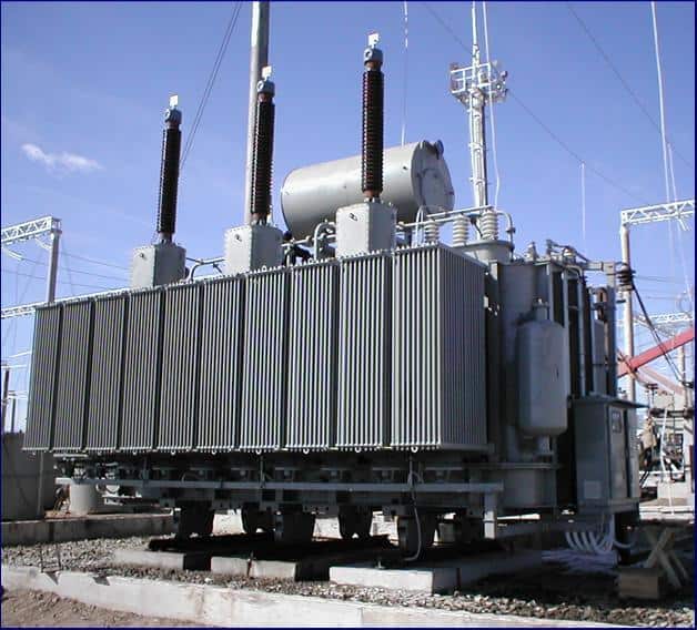
- Transformers (Power Transformers, Distribution Transformers, Traction Transformers, HVDC Converters, Solid State Transformers (SST), Rectifier Transformers):
- A transformer is a passive electrical device that transfers electrical energy from one circuit to another through electromagnetic induction. It can be classified into three types based on voltage change:
- Step-up: Increases voltage and decreases current.
- Step-down: Decreases voltage and increases current.
- Isolation: Provides electrical isolation without changing the voltage.
- Distribution vs. Power Transformers:
- Power Transformers: These are used in high-voltage transmission networks for both stepping up and stepping down applications (e.g., 400 kV, 220 kV). They are generally rated above ~100–200 MVA (not a strict boundary) and are designed for maximum efficiency at or near full load.
- Distribution Transformers: These are used in lower-voltage distribution networks to connect to end-users (e.g., 11 kV → 400/230 V). They are generally rated below ~100 MVA (typically much smaller in practice) and are designed for maximum efficiency at partial load (~50–70%), as they operate continuously with variable demand. They perform the final voltage transformation for household and commercial use.
- Specialized Transformers:
- Traction Transformers: These are special transformers used in railway systems to step down high-voltage AC power from the overhead catenary to the required voltage for the train’s traction system. They are typically standard grid-frequency transformers (50/60 Hz).
- HVDC Converter Transformers: Used in HVDC stations. These transformers adapt AC voltage levels and provide galvanic isolation and phase shifting before conversion to DC (rectification) or after inversion back to AC.
- Solid State Transformers (SSTs): Also known as power electronic transformers (PETs) or intelligent universal transformers (IUTs). These are power-electronic-based conversion systems (not purely AC-AC transformers) that include AC/DC/AC conversion stages with a high-frequency transformer, enabling reduced size, advanced control, and bidirectional power flow.
- Rectifier Transformers: These transformers supply AC power to rectifier systems, which convert it into DC. Their design minimizes harmonics and ensures stable DC output. They are used in industrial processes requiring large DC power (e.g., electrolysis, traction, HVDC).
- A transformer is a passive electrical device that transfers electrical energy from one circuit to another through electromagnetic induction. It can be classified into three types based on voltage change:

- Shunt Reactor:
- Shunt reactors are used in high-voltage transmission systems to control voltage during load variations.
- A shunt reactor is a device that absorbs reactive power (inductive compensation), thereby stabilizing voltage and improving system efficiency, especially in long transmission lines and cable systems.
- A shunt reactor can be directly connected to the power line or to a tertiary winding of a three-winding transformer. It can be permanently connected or switched via a circuit breaker.
- Unlike a power transformer, a shunt reactor typically has a single winding per phase and is designed to consume reactive power rather than transfer active power.
- Supply Chain:
- A supply chain is the end-to-end network of individuals, organizations, resources, activities, data, and technologies involved in the creation and delivery of a product or service—from raw materials to the final customer.
- A supply chain includes not only physical flows (goods), but also information flows and financial flows across all participants.
- At the most fundamental level, Supply Chain Management (SCM) is the integrated planning, coordination, and optimization of the flow of:
- goods
- information
- and finances
- from raw material sourcing to final delivery.
- At its core, SCM is not just “management of flows” but the optimization of those flows across cost, service level, speed, and risk.
- Supply Chain vs Logistics:
- Supply Chain: entire ecosystem (end-to-end)
- Logistics: subset focused on movement and storage of goods
- Transmission System Operator (TSO):
- A Transmission System Operator (TSO) is an entity entrusted with operating, maintaining, and developing the high-voltage electricity transmission network at a national or regional level, including ensuring the reliable operation and security of the transmission system. In the gas sector, a TSO performs comparable functions for high-pressure gas transmission networks, but electricity and gas TSOs are separate concepts.
- The TSO is responsible for transporting bulk energy over long distances, ensuring system-wide real-time balance between supply and demand, and maintaining grid stability (frequency, voltage, reliability). In electricity systems, TSOs also coordinate system operation, manage congestion and system security, and facilitate the integration of generation, interconnections, and other system resources.
- The term is defined by the European Commission. In the EU, the role and responsibilities of electricity TSOs are established through EU legislation and related network codes, rather than being simply a term defined by the European Commission.
- Distribution System Operators (DSO) and Distribution Network Operators (DNO):
- Entities responsible for operating, maintaining, and developing the medium- and low-voltage distribution networks, delivering energy from the transmission system (or distributed generation) to final consumers. Depending on the country and network structure, the distribution system may also include other voltage levels and directly connected generation or customers.
- DSOs increasingly manage bidirectional energy flows (from distributed energy resources like solar PV, EVs, storage), not just one-way distribution. They may also actively manage network constraints, voltage, congestion, flexibility, and the connection of distributed energy resources.
- Digitalisation is a key enabler of the DSO model, requiring investments in automation, smart meters, grid monitoring, real-time control systems, and data analytics.
- A DNO (Distribution Network Operator) already performs much of the tasks that a DSO does, but there are differences. In many contexts, DNO and DSO refer to essentially the same distribution-network operator, while “DSO” increasingly emphasizes the broader active-system-management role required by distributed generation, flexible demand, storage, and other distributed energy resources. The exact terminology and legal responsibilities vary by country.
- A conventional distribution network is not an active but a passive (or reactive) network. Passive distribution networks are designed to accept bulk power from the transmission system and distribute it downstream to consumers. Traditionally, distribution networks were predominantly operated as passive, one-way systems, with power flowing mainly from the transmission network toward consumers. Modern distribution networks are increasingly active, with bidirectional power flows and active management of distributed resources.
- =>DNO vs. DSO:
- DNO: operates a passive, one-way distribution network (traditional model) → traditionally operated mainly as a passive network, although a DNO can also operate an increasingly active network.
- DSO: operates an active, flexible network that manages distributed generation, demand response, and grid optimization → emphasizes active management of distributed resources, flexibility, network constraints, and increasingly decentralized power flows.