Hitachi Energy – Hitachi Energy and Blykalla collaborate to advance next-generation nuclear power technology

- The collaboration combines electrification and grid management software expertise with next generation lead-cooled advanced modular reactors (AMR) at a time when the demand for fossil-free electricity surges globally
- Meets electricity demand from energy-intensive industries, data centers and society
Hitachi Energy, a global leader in electrification and Blykalla, a global leader in advanced nuclear technology today announced the signing of a Memorandum of Understanding (MoU) to explore a long-term collaboration on enabling the deployment of next-generation lead-cooled advanced modular reactors.
The collaboration brings together Blykalla’s advanced reactor technology with Hitachi Energy’s expertise in electrification, grid integration, and energy industry software to support the integration of reliable, fossil-free power into future energy systems. Through a MoU, the companies will jointly optimize the electrical and grid integration design for Blykalla’s reactor type, covering transmission-level connection, on-site electrical systems, and digital monitoring. It also enables Hitachi Energy to integrate its offering into a standard solution for small modular reactors (SMR).
Focus areas includes, but not limited to, conceptual designs for grid connection and network integration, on-site electrical architecture, digital tools for construction and operation, and a combined offering for customers with the highest, most constant power demands, beginning with data centers and energy-intensive industry.
As global electricity demand accelerates – driven by electrification of industry, transport and society – there is a growing need for stable, carbon-free power sources that complement renewable energy. AMRs can play an important role in delivering fossil-free baseload power to energy-intensive industries and emerging applications, such as datacenters.

“We need reliable and low-carbon power solutions that can be integrated efficiently into the energy system as electricity demand continues to grow across industry and digital infrastructure.
By combining Blykalla’s innovative reactor technology with our expertise in electrification, we can help enable solutions that support industrial growth and the broader energy transition.”
Tobias Hansson, Country Managing Director of Hitachi Energy Sweden
“As we move toward commercialization, this collaboration strengthens our ability to deliver complete energy solutions.
Hitachi Energy’s expertise in electrification makes them a strong partner to help bring our technology to market, and positions us to meet the growing global demand for clean, reliable power.”
Jacob Stedman, CEO of Blykalla
By integrating Blykalla´s power generation with Hitachi Energy´s solutions for electrical infrastructure, the collaboration aims to accelerate the commercialization and deployment of advanced nuclear solutions across Europe and the United States.
The collaboration reflects the shared ambition of both companies to accelerate innovation and support the transition toward a more sustainable, secure, and resilient energy system.
Advancing next-generation nuclear technology
Blykalla’s innovative AMR uses proven lead-cooling technology. With their breakthrough materials innovation, Blykalla utilizes proprietary and patented aluminum alloyed steels that can withstand the corrosive nature of liquid lead, thereby enabling commercialization of lead-cooled fast reactors.
The technology builds on proven concepts, further developed through Swedish research and innovation.
SourceHitachi Energy
EMR Analysis
More information on Hitachi Ltd.: https://www.hitachi.com + Through its Social Innovation Business (SIB) that brings together IT, OT (Operational Technology) and products, Hitachi aims to be a global leader in continuously transforming social infrastructure through digital, contributing to a harmonized society where the environment, wellbeing, and economic growth are in balance. Hitachi operates worldwide across four sectors – Digital Systems & Services, Energy, Mobility, and Connective Industries – as well as a Strategic SIB Business Unit focused on new growth areas. With Lumada at its core, Hitachi creates value by combining data, technology and domain knowledge to solve customer and social challenges. Revenues for FY2025 (ended March 31, 2026) totaled 10,586.7 billion yen, with 606 consolidated subsidiaries and approximately 290,000 employees worldwide.
More information on Toshiaki Higashihara (Executive Chairman, Hitachi Ltd.): https://www.hitachi.com/corporate/about/officers/index.html#toshiaki-higashihara
More information on Toshiaki Tokunaga (President & Chief Executive Officer, Hitachi Ltd.): https://www.hitachi.com/New/cnews/month/2024/12/f_241216.pdf + https://www.linkedin.com/in/toshiaki-tokunaga-7113381aa/
More information on Hitachi Energy by Hitachi Ltd.: See the full profile on EMR Executive Services
More information on Andreas Schierenbeck (Senior Vice President and Executive Officer, Head of Energy Business, Hitachi, Ltd. + Chief Executive Officer, Hitachi Energy Ltd.): See the full profile on EMR Executive Services
More information on Ismo Haka (Chief Financial Officer and Executive Vice President, Hitachi Energy, Hitachi Energy Ltd.): See the full profile on EMR Executive Services
More information on Tobias Hansson (Country Managing Director, Hitachi Energy Sweden AB, Hitachi Energy): See the full profile on EMR Executive Services
More information on Blykalla: https://www.blykalla.com/ + Blykalla is a global leader in advanced nuclear technology, commercializing the next generation of clean, reliable energy through its lead-cooled reactor, the SEALER. Blykalla’s work is built on an industry legacy of quality, safety, and excellence. By combining decades of specialized research with world-class partners, Blykalla is building the backbone of the global AI and industrial economy.
More information on Jacob Stedman (Chief Executive Officer, Blykalla): https://www.blykalla.com/about-us + https://www.linkedin.com/in/jstedman/
EMR Additional Notes:
- Grid, Microgrids, DERs and DERM’s:
- Grid / Power Grid:
- The power grid is a network for delivering electricity to consumers. The power grid includes generator stations, transmission lines and towers, and distribution networks.
- The grid constantly balances the supply and demand for the energy that powers everything from industry to household appliances.
- Electric grids perform three major functions: generation, transmission, and distribution
- Microgrid:
- Small-scale power grid that can operate independently or collaboratively with other grids. The practice of using microgrids is known as distributed, dispersed, decentralized, district or embedded energy production.
- Group of interconnected loads and DERs (Distributed Energy Resources) within clearly defined electrical and geographical boundaries which acts as a single controllable entity with respect to the main grid.
- A microgrid can operate in both grid-connected mode and islanded (off-grid) mode.
- Smart Grid:
- An electrical grid enhanced with digital communication, automation, and IT systems across generation, transmission, distribution, and consumption levels.
- Enables real-time monitoring, control, demand response, and integration of DERs.
- Distributed Energy Resources (DERs):
- Small-scale electricity supply and demand-side resources (typically in the range of a few kW up to tens of MW, depending on definition) that are interconnected to the electric grid. They are power generation resources and are usually located close to load centers, and can be used individually or in aggregate to provide value to the grid.
- Common examples of DERs include rooftop solar PV units, natural gas turbines, microturbines, wind turbines, biomass generators, fuel cells, tri-generation units, battery storage, electric vehicles (EV) and EV chargers, and demand response resources (load flexibility).
- Distributed Energy Resources Management Systems (DERMS):
- Platforms which help mostly distribution system operators (DSO) manage their grids that are mainly based on distributed energy resources (DER).
- DERMS are used by utilities and other energy companies to aggregate and orchestrate distributed energy resources for participation in the demand response market and grid services (e.g., flexibility, voltage control, congestion management).
- Grid / Power Grid:
- Hardware vs. Software vs. Firmware:
- Hardware is physical: it’s tangible electronic or mechanical components. It can break, wear out, or be damaged by environmental factors (heat, water, shock, etc.).
- Since hardware is part of the “real” world, it all eventually wears out. Being a physical thing, it’s also possible to break it, drown it, overheat it, and otherwise expose it to the elements.
- Here are some examples of hardware:
- Smartphone
- Tablet
- Laptop
- Desktop computer
- Printer
- Flash drive
- Router
- Software is virtual: it consists of programs and data that run on hardware to perform functions. It can be copied, modified, updated, or deleted.
- Software is everything about your computer that isn’t hardware.
- Here are some examples of software:
- Operating systems like Windows 11 or iOS
- Web browsers
- Antivirus tools
- Adobe Photoshop
- Mobile apps
- Firmware is virtual: is embedded software that is tightly coupled to specific hardware and controls its low-level functions.
- While not as common a term as hardware or software, firmware is everywhere—on your smartphone, your PC’s motherboard, your camera, your headphones, and even your TV remote control.
- Firmware is a specialized type of software that serves a specific control and interface role between hardware and higher-level software.
- Hardware is physical: it’s tangible electronic or mechanical components. It can break, wear out, or be damaged by environmental factors (heat, water, shock, etc.).
- Small Modular Reactors (SMR):
- Small modular reactors (SMRs) are advanced nuclear reactors that have a power capacity of up to 300 MW(e) per unit, which is about one-third of the generating capacity of traditional nuclear power reactors. SMRs, which can produce a large amount of low-carbon electricity, are:
- Small – physically a fraction of the size of a conventional nuclear power reactor.
- Modular – making it possible for systems and components to be factory-assembled and transported as a unit to a location for installation.
- Reactors – harnessing nuclear fission to generate heat to produce energy.
- Small modular reactors (SMRs) are advanced nuclear reactors that have a power capacity of up to 300 MW(e) per unit, which is about one-third of the generating capacity of traditional nuclear power reactors. SMRs, which can produce a large amount of low-carbon electricity, are:
- Advanced Modular Reactors (AMR):
- Advanced Modular Reactors (AMRs) are a class of next-generation nuclear reactor designs that represent a significant departure from the large, conventional nuclear power plants currently in operation. They are considered part of advanced / Generation IV (and some late Generation III+) nuclear technologies, depending on design maturity and are often used interchangeably with the term “Small Modular Reactors” (SMRs) in a broader sense, especially when they use coolants other than light water.
- AMR (Advanced Modular Reactor) is a subset of SMRs defined primarily by its technology (coolant, fuel type, safety concept), not just size or modularity.
- While all AMRs are also SMRs due to their small and modular nature, not all SMRs are AMRs. Some SMRs use conventional, light-water reactor technology scaled down to a smaller size. AMRs, on the other hand, utilize a new, “advanced” class of technologies and coolants (like gas, molten salt, or liquid metal) that are fundamentally different from traditional reactors.
- MoU (Memorandum of Understanding):
- A Memorandum of Understanding (MoU) is a formalized statement of intent between parties, describing how they plan to work together toward a common goal. It expresses a convergence of intent between the parties and defines the objectives, principles, scope, and framework of a potential collaboration.
- An MoU is often the starting point of negotiations or a future business relationship, allowing multiple parties to signal their intent to collaborate, negotiate, or reach a future agreement. It simplifies the negotiation process by establishing the key objectives, responsibilities, and goals before drafting a more detailed contract, where appropriate.
- An MoU is not necessarily a legally binding document. It is a statement of serious intent—agreed voluntarily by equal partners—that outlines the commitment, roles, resources, and expectations that each of the parties will bring. It is often non-binding, but certain provisions (such as confidentiality, exclusivity, or dispute resolution) may be legally binding depending on its wording and the applicable jurisdiction.
- Carbon Dioxide (CO2):
- The primary greenhouse gas emitted through human activities. Carbon dioxide enters the atmosphere through the burning of fossil fuels (coal, natural gas, and oil), solid waste, biomass (e.g. wood), and also as a result of certain industrial chemical reactions (e.g. cement production).
- Carbon dioxide is removed from the atmosphere (or “sequestered”) when it is absorbed by plants as part of the biological carbon cycle and through ocean absorption and geological processes.
- CO₂ is naturally part of the carbon cycle, but human activities have significantly increased its concentration in the atmosphere.
- Biogenic Carbon Dioxide (CO2):
- Biogenic CO₂ and fossil-derived CO₂ are chemically identical molecules.
- The distinction is not chemical, but source-based:
- Biogenic carbon: CO₂ released from organic materials such as plants, wood, soil, and biomass that were recently part of the natural carbon cycle.
- Fossil carbon: CO₂ released from fossil fuels (coal, oil, gas), which were stored underground for millions of years.
- CO2e (Carbon Dioxide Equivalent):
- CO₂e means “carbon dioxide equivalent”.
- It is a standardized climate metric used to express the total climate impact of multiple greenhouse gases in a single standardized unit.
- CO₂e converts all greenhouse gases (such as methane and nitrous oxide) into the amount of CO₂ that would have the same global warming effect over a defined time period.
- Formula: CO₂e = mass of gas × Global Warming Potential (GWP)
- Carbon dioxide equivalents are commonly expressed as million metric tonnes of carbon dioxide equivalents, abbreviated as MMTCDE.
- The carbon dioxide equivalent for a gas is derived by multiplying the tonnes of the gas by the associated GWP: MMTCDE = (million metric tonnes of a gas) * (GWP of the gas).
- For example, the GWP for methane is 25 and for nitrous oxide 298. This means that emissions of 1 million metric tonnes of methane and nitrous oxide respectively is equivalent to emissions of 25 and 298 million metric tonnes of carbon dioxide.
- Carbon Footprint:
- There is no universally agreed definition of what a carbon footprint is.
- The most widely used definition (GHG Protocol) describes it as: “The total set of greenhouse gas (GHG) emissions caused directly and indirectly through an organization’s operations and value chain.”
- A carbon footprint is the total amount of greenhouse gas (GHG) emissions caused directly and indirectly by an individual, organization, product, or activity.
- It is typically measured in CO₂e.
- Decarbonization:
- Reduction of carbon dioxide emissions through the use of low-carbon energy sources and improved efficiency, with the goal of reducing overall greenhouse gas emissions.
- Decarbonization typically refers to system-wide transition, not only emission reduction at a single source.
- Carbon Credits or Carbon Offsets:
- Carbon credits are tradable certificates representing the right to emit one metric ton of CO₂e.
- They are part of cap-and-trade systems, where:
- A cap limits total emissions
- Companies receive or buy allowances
- Excess credits can be traded
- Offsets are often linked to external projects that reduce or remove emissions (e.g. reforestation, renewable energy).
- Carbon Capture and Storage (CCS) – Carbon Capture, Utilisation and Storage (CCUS):
- CCS involves capturing CO₂ emissions from industrial processes and storing them permanently in geological formations (e.g. underground reservoirs).
- CCUS adds a utilization step, where captured CO₂ is reused as a feedstock (e.g. fuels, chemicals, building materials).
- CCS = storage only, CCUS = storage + reuse.
- Carbon Dioxide Removal (CDR) or Durable Carbon Removal:
- CDR refers to methods that actively remove CO₂ from the atmosphere and store it for long periods in geological, biological, or mineral form.
- Examples include:
- Direct Air Capture (DAC)
- Bioenergy with Carbon Capture (BECCS)
- Enhanced Rock Weathering (ERW)
- CDR creates net negative emissions when removal exceeds emissions.
- Direct Air Capture (DAC):
- Technologies that extract CO2 directly from the atmosphere at any location, unlike carbon capture which is generally carried out at the point of emissions, such as a steel plant.
- Constraints like costs and energy requirements as well as the potential for pollution make DAC a less desirable option for CO2 reduction. Its larger land footprint when compared to other mitigation strategies like carbon capture and storage systems (CCS) also put it at a disadvantage.
- Direct Air Capture and Storage (DACCS):
- Climate technology that removes carbon dioxide (CO2) directly from the ambient atmosphere using large fans and chemical processes to bind with the CO2.
- Bioenergy with Carbon Capture and Storage (BECCS):
- Technology that generates energy from biomass while capturing and storing the resulting CO₂.
- Because biomass absorbs CO₂ while growing, BECCS can result in net negative emissions.
- Enhanced Rock Weathering (ERW):
- Carbon dioxide removal (CDR) technique that accelerates the natural process of rock weathering by grinding silicate rocks into dust and spreading it on land, typically agricultural fields. This process uses rainwater to convert atmospheric carbon dioxide into mineral carbonates, which are then stored long-term in soils, groundwater, and oceans.
- Limits of Carbon Dioxide Storage:
- Carbon storage is not endless; the Earth’s capacity for permanently storing vast amounts of captured carbon, particularly in geological formations, is limited, potentially reaching a critical limit of 1,460 gigatonnes at around 2200, though storage durations vary significantly depending on the method, from decades for some biological methods to potentially millions of years for others like mineralization. While some methods offer very long-term storage, the sheer volume needed to meet climate targets requires scaling up storage significantly beyond current capacity, raising concerns about the available volume over time.
- Carbon Impregnation:
- Carbon impregnation is the process of treating activated carbon with chemical agents (such as metals, acids, or bases) to enhance its ability to adsorb specific, hard-to-remove pollutants. By loading substances like silver, sulfur, or potassium hydroxide into its pores, this material combines physical adsorption with chemical reaction for improved, targeted filtration in water and air. This is a materials engineering process, not a climate accounting concept.
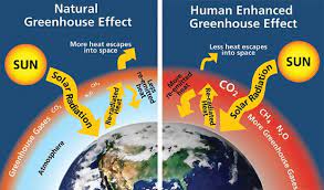
- Global Warming:
- Global warming is the long-term heating of Earth’s climate system observed since the pre-industrial period (between 1850 and 1900) due to human activities, primarily fossil fuel burning, which increases heat-trapping greenhouse gas levels in Earth’s atmosphere.
- Global Warming Potential (GWP):
- A measure of how much heat a greenhouse gas traps in the atmosphere compared to CO₂ over a specific time period (commonly 100 years).
- CO₂ has a GWP of 1.
- GWP is the scientific basis for converting gases into CO₂e.
- GWP was developed to allow comparisons of the global warming impacts of different gases.
- Greenhouse Gas (GHG):
- Any gas that absorbs and traps infrared radiation in the atmosphere, contributing to the greenhouse effect.
- Main GHGs include:
- CO₂
- Methane (CH₄)
- Nitrous oxide (N₂O)
- Fluorinated gases
- Water vapor is a GHG but is not directly controlled by human emissions at scale.
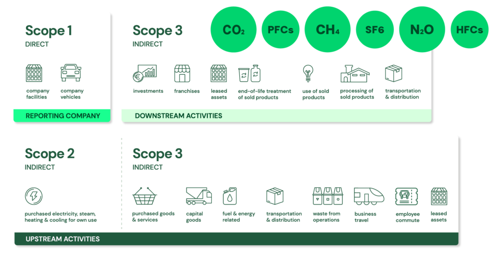
- GHG Protocol Corporate Standard Scope 1, 2 and 3: https://ghgprotocol.org/ + The GHG Protocol Corporate Accounting and Reporting Standard provides requirements and guidance for companies and other organizations preparing a corporate-level GHG emissions inventory. Scope 1 and 2 are typically mandatory for companies that are required to report their emissions by national or regional regulations. The GHG Protocol itself is a voluntary standard.
- Scope 1: Direct emissions:
- Direct emissions from company-owned and controlled resources. In other words, emissions are released into the atmosphere as a direct result of a set of activities, at a firm level. It is divided into four categories:
- Stationary combustion (e.g from fuels, heating sources). All fuels that produce GHG emissions must be included in scope 1.
- Mobile combustion is all vehicles owned or controlled by a firm, burning fuel (e.g. cars, vans, trucks). The increasing use of “electric” vehicles (EVs), means that some of the organisation’s fleets could fall into Scope 2 emissions.
- Fugitive emissions are leaks from greenhouse gases (e.g. refrigeration, air conditioning units). It is important to note that refrigerant gases are a thousand times more dangerous than CO2 emissions. Companies are encouraged to report these emissions.
- Process emissions are released during industrial processes, and on-site manufacturing (e.g. production of CO2 during cement manufacturing, factory fumes, chemicals).
- Direct emissions from company-owned and controlled resources. In other words, emissions are released into the atmosphere as a direct result of a set of activities, at a firm level. It is divided into four categories:
- Scope 2: Indirect emissions – owned:
- Indirect emissions from the generation of purchased energy, from a utility provider. In other words, all GHG emissions released in the atmosphere, from the consumption of purchased electricity, steam, heat and cooling. For most organisations, electricity will be the unique source of scope 2 emissions. Simply stated, the energy consumed falls into two scopes: Scope 2 covers the electricity consumed by the end-user. Scope 3 covers the energy used by the utilities during transmission and distribution (T&D losses).
- Scope 3: Indirect emissions – not owned:
- Indirect emissions – not included in scope 2 – that occur in the value chain of the reporting company, including both upstream and downstream emissions. In other words, emissions are linked to the company’s operations. According to the GHG protocol, scope 3 emissions are separated into 15 categories.
- Scope 1: Direct emissions: