HItachi Energy – Hitachi Energy inaugurates power transformers factory and service center in Dilovası, Türkiye
New advanced low-carbon facility strengthens manufacturing capacity and service capabilities, expands export reach, and supports the growing energy transition demand across Türkiye and global markets.
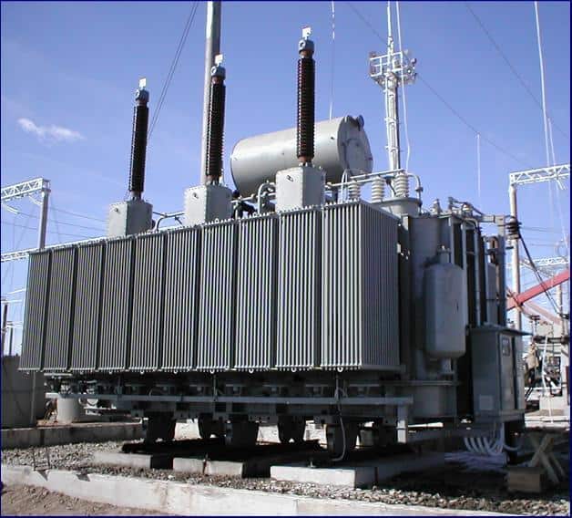
Hitachi Energy today celebrates a major milestone with the inauguration of its new Power Transformers Factory and Service Center in Dilovası, Türkiye. The new facility represents a strategic investment to strengthen manufacturing capacity, service capabilities, and support the accelerating energy transition across Türkiye and key export markets.
With a transformer manufacturing heritage in Türkiye dating back to 1965, Hitachi Energy has played an important role in supporting the country’s industrial growth, grid development, and critical infrastructure for decades. The Dilovası inauguration marks the next chapter of that legacy, reinforcing Türkiye’s position as an important industrial and energy hub connecting Europe, Asia, the Middle East, and Africa.
“As demand for reliable, efficient, and sustainable electricity continues to grow, investments, such as Dilovası are essential to strengthening energy systems and supporting long-term economic development.
This new factory reflects our continued confidence in Türkiye and our commitment to serving customers with world-class technology, local expertise, and faster delivery capabilities.”
Carlos Pettinau
Hub APMEA Manager
Business Unit Transformers
Hitachi Energy
“With the new service center in Dilovasi, we are expanding our capabilities and supporting our growing customer base, while delivering faster and more flexible service solutions.
As a lifecycle partner, with more than 60 years of operation in Türkiye, we are future proofing our customers through improved responsiveness and closer proximity to our installed base.”
Jonas Wernli
Europe Manager
Service Business
Hitachi Energy
The new facility embodies Hitachi Energy’s commitment to advanced technology, exceptional quality, and world-class manufacturing standards. It is designed to produce a complete range of small, medium, and large power transformers, supporting utilities, renewables, industry, transportation, and data centers. The site also strengthens export capacity, serving customers in more than 50 countries worldwide.
The Service Center strengthens Hitachi Energy’s lifecycle service offerings by delivering comprehensive solutions at every stage of the asset lifecycle – from consulting to installation and commissioning of new equipment to regular assessments, parts and maintenance to upgrades, repairs and lifetime extension – supporting customers to improve operational performance, and ensuring more secure, resilient and efficient energy systems.
This investment also contributes to the company’s broader global expansion strategy to meet rising demand driven by electrification, renewable integration, grid modernization, and digital infrastructure growth.
Sustainability is embedded throughout the factory’s design and operations. Built as an ultra-low-carbon facility, the site is designed to reduce carbon emissions by around 95 percent with renewable electricity, energy-efficient systems, solar integration, advanced HVAC technologies, and water conservation measures including rainwater harvesting and gray water reuse.
The Dilovası facility is expected to increase workforce capacity by around 30 percent, creating new opportunities for skilled talent while contributing to local development.
The inauguration ceremony welcomed customers, business partners, government representatives, and company leaders to celebrate a new milestone that will help power industries, cities, and communities for decades to come.
SourceHitachi Energy
EMR Analysis
More information on Hitachi Ltd.: https://www.hitachi.com + Through its Social Innovation Business (SIB) that brings together IT, OT (Operational Technology) and products, Hitachi aims to be a global leader in continuously transforming social infrastructure through digital, contributing to a harmonized society where the environment, wellbeing, and economic growth are in balance. Hitachi operates worldwide across four sectors – Digital Systems & Services, Energy, Mobility, and Connective Industries – as well as a Strategic SIB Business Unit focused on new growth areas. With Lumada at its core, Hitachi creates value by combining data, technology and domain knowledge to solve customer and social challenges. Revenues for FY2025 (ended March 31, 2026) totaled 10,586.7 billion yen, with 606 consolidated subsidiaries and approximately 290,000 employees worldwide.
More information on Toshiaki Higashihara (Executive Chairman, Hitachi Ltd.): https://www.hitachi.com/corporate/about/officers/index.html#toshiaki-higashihara
More information on Toshiaki Tokunaga (President & Chief Executive Officer, Hitachi Ltd.): https://www.hitachi.com/New/cnews/month/2024/12/f_241216.pdf + https://www.linkedin.com/in/toshiaki-tokunaga-7113381aa/
More information on Hitachi Energy by Hitachi Ltd.: See the full profile on EMR Executive Services
More information on Andreas Schierenbeck (Senior Vice President and Executive Officer, Head of Energy Business, Hitachi, Ltd. + Chief Executive Officer, Hitachi Energy Ltd.): See the full profile on EMR Executive Services
More information on Ismo Haka (Chief Financial Officer and Executive Vice President, Hitachi Energy, Hitachi Energy Ltd.): See the full profile on EMR Executive Services
More information on Business Unit Transformers by Hitachi Energy: See the full profile on EMR Executive Services
More information on Bruno Melles (Managing Director, Business Unit Transformers, Hitachi Energy): See the full profile on EMR Executive Services
More information on Carlos Pettinau (Hub Manager APMEA, Business Unit Transformers, Hitachi Energy): See the full profile on EMR Executive Services
More information on Business Unit Service by Hitachi Energy: See the full profile on EMR Executive Services
More information on Wolfgang Mueller (Executive Vice President and Business Unit (BU) Managing Director, Service Business, Hitachi Energy): See the full profile on EMR Executive Services
More information on Jonas Wernli (Global Product Group Transformers Service Manager and Europe Manager, Service Business, Hitachi Energy): See the full profile on EMR Executive Services
EMR Additional Notes:
- Substation:
- A power station is where the power is generated. A substation is a critical part of an electrical transmission and distribution system (not generation itself), where power is transformed, switched, controlled, and distributed further into the grid.
- Substations contain specialized equipment that allows the voltage of electricity to be transformed and controlled. The voltage is stepped up or down through transformers located within the substation.
- Substations also perform protection, monitoring, and grid control functions—not just voltage transformation.
- Substations typically include:
- Transformers: The core components for voltage transformation.
- Circuit Breakers: To isolate and protect equipment.
- Switchgear: For controlling and protecting the flow of electricity.
- Shunt Reactors (sometimes): Used to improve system stability.
- Other equipment: Measuring instruments, control panels, etc.
- Transformers (Power Transformers, Distribution Transformers, Traction Transformers, HVDC Converters, Solid State Transformers (SST), Rectifier Transformers):
- A transformer is a passive electrical device that transfers electrical energy from one circuit to another through electromagnetic induction. It can be classified into three types based on voltage change:
- Step-up: Increases voltage and decreases current.
- Step-down: Decreases voltage and increases current.
- Isolation: Provides electrical isolation without changing the voltage.
- Distribution vs. Power Transformers:
- Power Transformers: These are used in high-voltage transmission networks for both stepping up and stepping down applications (e.g., 400 kV, 220 kV). They are generally rated above ~100–200 MVA (not a strict boundary) and are designed for maximum efficiency at or near full load.
- Distribution Transformers: These are used in lower-voltage distribution networks to connect to end-users (e.g., 11 kV → 400/230 V). They are generally rated below ~100 MVA (typically much smaller in practice) and are designed for maximum efficiency at partial load (~50–70%), as they operate continuously with variable demand. They perform the final voltage transformation for household and commercial use.
- Specialized Transformers:
- Traction Transformers: These are special transformers used in railway systems to step down high-voltage AC power from the overhead catenary to the required voltage for the train’s traction system. They are typically standard grid-frequency transformers (50/60 Hz).
- HVDC Converter Transformers: Used in HVDC stations. These transformers adapt AC voltage levels and provide galvanic isolation and phase shifting before conversion to DC (rectification) or after inversion back to AC.
- Solid State Transformers (SSTs): Also known as power electronic transformers (PETs) or intelligent universal transformers (IUTs). These are power-electronic-based conversion systems (not purely AC-AC transformers) that include AC/DC/AC conversion stages with a high-frequency transformer, enabling reduced size, advanced control, and bidirectional power flow.
- Rectifier Transformers: These transformers supply AC power to rectifier systems, which convert it into DC. Their design minimizes harmonics and ensures stable DC output. They are used in industrial processes requiring large DC power (e.g., electrolysis, traction, HVDC).
- A transformer is a passive electrical device that transfers electrical energy from one circuit to another through electromagnetic induction. It can be classified into three types based on voltage change:

- Shunt Reactor:
- Shunt reactors are used in high-voltage transmission systems to control voltage during load variations.
- A shunt reactor is a device that absorbs reactive power (inductive compensation), thereby stabilizing voltage and improving system efficiency, especially in long transmission lines and cable systems.
- A shunt reactor can be directly connected to the power line or to a tertiary winding of a three-winding transformer. It can be permanently connected or switched via a circuit breaker.
- Unlike a power transformer, a shunt reactor typically has a single winding per phase and is designed to consume reactive power rather than transfer active power.
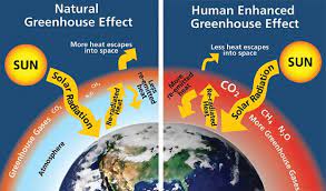
- Carbon Dioxide (CO2):
- The primary greenhouse gas emitted through human activities. Carbon dioxide enters the atmosphere through the burning of fossil fuels (coal, natural gas, and oil), solid waste, biomass (e.g. wood), and also as a result of certain industrial chemical reactions (e.g. cement production).
- Carbon dioxide is removed from the atmosphere (or “sequestered”) when it is absorbed by plants as part of the biological carbon cycle and through ocean absorption and geological processes.
- CO₂ is naturally part of the carbon cycle, but human activities have significantly increased its concentration in the atmosphere.
- Biogenic Carbon Dioxide (CO2):
- Biogenic CO₂ and fossil-derived CO₂ are chemically identical molecules.
- The distinction is not chemical, but source-based:
- Biogenic carbon: CO₂ released from organic materials such as plants, wood, soil, and biomass that were recently part of the natural carbon cycle.
- Fossil carbon: CO₂ released from fossil fuels (coal, oil, gas), which were stored underground for millions of years.
- CO2e (Carbon Dioxide Equivalent):
- CO₂e means “carbon dioxide equivalent”.
- It is a standardized climate metric used to express the total climate impact of multiple greenhouse gases in a single standardized unit.
- CO₂e converts all greenhouse gases (such as methane and nitrous oxide) into the amount of CO₂ that would have the same global warming effect over a defined time period.
- Formula: CO₂e = mass of gas × Global Warming Potential (GWP)
- Carbon dioxide equivalents are commonly expressed as million metric tonnes of carbon dioxide equivalents, abbreviated as MMTCDE.
- The carbon dioxide equivalent for a gas is derived by multiplying the tonnes of the gas by the associated GWP: MMTCDE = (million metric tonnes of a gas) * (GWP of the gas).
- For example, the GWP for methane is 25 and for nitrous oxide 298. This means that emissions of 1 million metric tonnes of methane and nitrous oxide respectively is equivalent to emissions of 25 and 298 million metric tonnes of carbon dioxide.
- Carbon Footprint:
- There is no universally agreed definition of what a carbon footprint is.
- The most widely used definition (GHG Protocol) describes it as: “The total set of greenhouse gas (GHG) emissions caused directly and indirectly through an organization’s operations and value chain.”
- A carbon footprint is the total amount of greenhouse gas (GHG) emissions caused directly and indirectly by an individual, organization, product, or activity.
- It is typically measured in CO₂e.
- Decarbonization:
- Reduction of carbon dioxide emissions through the use of low-carbon energy sources and improved efficiency, with the goal of reducing overall greenhouse gas emissions.
- Decarbonization typically refers to system-wide transition, not only emission reduction at a single source.
- Carbon Credits or Carbon Offsets:
- Carbon credits are tradable certificates representing the right to emit one metric ton of CO₂e.
- They are part of cap-and-trade systems, where:
- A cap limits total emissions
- Companies receive or buy allowances
- Excess credits can be traded
- Offsets are often linked to external projects that reduce or remove emissions (e.g. reforestation, renewable energy).
- Carbon Capture and Storage (CCS) – Carbon Capture, Utilisation and Storage (CCUS):
- CCS involves capturing CO₂ emissions from industrial processes and storing them permanently in geological formations (e.g. underground reservoirs).
- CCUS adds a utilization step, where captured CO₂ is reused as a feedstock (e.g. fuels, chemicals, building materials).
- CCS = storage only, CCUS = storage + reuse.
- Carbon Dioxide Removal (CDR) or Durable Carbon Removal:
- CDR refers to methods that actively remove CO₂ from the atmosphere and store it for long periods in geological, biological, or mineral form.
- Examples include:
- Direct Air Capture (DAC)
- Bioenergy with Carbon Capture (BECCS)
- Enhanced Rock Weathering (ERW)
- CDR creates net negative emissions when removal exceeds emissions.
- Direct Air Capture (DAC):
- Technologies that extract CO2 directly from the atmosphere at any location, unlike carbon capture which is generally carried out at the point of emissions, such as a steel plant.
- Constraints like costs and energy requirements as well as the potential for pollution make DAC a less desirable option for CO2 reduction. Its larger land footprint when compared to other mitigation strategies like carbon capture and storage systems (CCS) also put it at a disadvantage.
- Direct Air Capture and Storage (DACCS):
- Climate technology that removes carbon dioxide (CO2) directly from the ambient atmosphere using large fans and chemical processes to bind with the CO2.
- Bioenergy with Carbon Capture and Storage (BECCS):
- Technology that generates energy from biomass while capturing and storing the resulting CO₂.
- Because biomass absorbs CO₂ while growing, BECCS can result in net negative emissions.
- Enhanced Rock Weathering (ERW):
- Carbon dioxide removal (CDR) technique that accelerates the natural process of rock weathering by grinding silicate rocks into dust and spreading it on land, typically agricultural fields. This process uses rainwater to convert atmospheric carbon dioxide into mineral carbonates, which are then stored long-term in soils, groundwater, and oceans.
- Limits of Carbon Dioxide Storage:
- Carbon storage is not endless; the Earth’s capacity for permanently storing vast amounts of captured carbon, particularly in geological formations, is limited, potentially reaching a critical limit of 1,460 gigatonnes at around 2200, though storage durations vary significantly depending on the method, from decades for some biological methods to potentially millions of years for others like mineralization. While some methods offer very long-term storage, the sheer volume needed to meet climate targets requires scaling up storage significantly beyond current capacity, raising concerns about the available volume over time.
- Carbon Impregnation:
- Carbon impregnation is the process of treating activated carbon with chemical agents (such as metals, acids, or bases) to enhance its ability to adsorb specific, hard-to-remove pollutants. By loading substances like silver, sulfur, or potassium hydroxide into its pores, this material combines physical adsorption with chemical reaction for improved, targeted filtration in water and air. This is a materials engineering process, not a climate accounting concept.
- Global Warming:
- Global warming is the long-term heating of Earth’s climate system observed since the pre-industrial period (between 1850 and 1900) due to human activities, primarily fossil fuel burning, which increases heat-trapping greenhouse gas levels in Earth’s atmosphere.
- Global Warming Potential (GWP):
- A measure of how much heat a greenhouse gas traps in the atmosphere compared to CO₂ over a specific time period (commonly 100 years).
- CO₂ has a GWP of 1.
- GWP is the scientific basis for converting gases into CO₂e.
- GWP was developed to allow comparisons of the global warming impacts of different gases.
- Greenhouse Gas (GHG):
- Any gas that absorbs and traps infrared radiation in the atmosphere, contributing to the greenhouse effect.
- Main GHGs include:
- CO₂
- Methane (CH₄)
- Nitrous oxide (N₂O)
- Fluorinated gases
- Water vapor is a GHG but is not directly controlled by human emissions at scale.
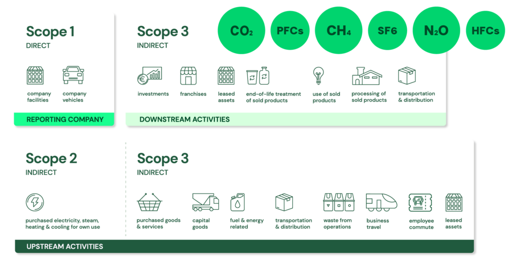
- GHG Protocol Corporate Standard Scope 1, 2 and 3: https://ghgprotocol.org/ + The GHG Protocol Corporate Accounting and Reporting Standard provides requirements and guidance for companies and other organizations preparing a corporate-level GHG emissions inventory. Scope 1 and 2 are typically mandatory for companies that are required to report their emissions by national or regional regulations. The GHG Protocol itself is a voluntary standard.
- Scope 1: Direct emissions:
- Direct emissions from company-owned and controlled resources. In other words, emissions are released into the atmosphere as a direct result of a set of activities, at a firm level. It is divided into four categories:
- Stationary combustion (e.g from fuels, heating sources). All fuels that produce GHG emissions must be included in scope 1.
- Mobile combustion is all vehicles owned or controlled by a firm, burning fuel (e.g. cars, vans, trucks). The increasing use of “electric” vehicles (EVs), means that some of the organisation’s fleets could fall into Scope 2 emissions.
- Fugitive emissions are leaks from greenhouse gases (e.g. refrigeration, air conditioning units). It is important to note that refrigerant gases are a thousand times more dangerous than CO2 emissions. Companies are encouraged to report these emissions.
- Process emissions are released during industrial processes, and on-site manufacturing (e.g. production of CO2 during cement manufacturing, factory fumes, chemicals).
- Direct emissions from company-owned and controlled resources. In other words, emissions are released into the atmosphere as a direct result of a set of activities, at a firm level. It is divided into four categories:
- Scope 2: Indirect emissions – owned:
- Indirect emissions from the generation of purchased energy, from a utility provider. In other words, all GHG emissions released in the atmosphere, from the consumption of purchased electricity, steam, heat and cooling. For most organisations, electricity will be the unique source of scope 2 emissions. Simply stated, the energy consumed falls into two scopes: Scope 2 covers the electricity consumed by the end-user. Scope 3 covers the energy used by the utilities during transmission and distribution (T&D losses).
- Scope 3: Indirect emissions – not owned:
- Indirect emissions – not included in scope 2 – that occur in the value chain of the reporting company, including both upstream and downstream emissions. In other words, emissions are linked to the company’s operations. According to the GHG protocol, scope 3 emissions are separated into 15 categories.
- Scope 1: Direct emissions:
- Grid, Microgrids, DERs and DERM’s:
- Grid / Power Grid:
- The power grid is a network for delivering electricity to consumers. The power grid includes generator stations, transmission lines and towers, and distribution networks.
- The grid constantly balances the supply and demand for the energy that powers everything from industry to household appliances.
- Electric grids perform three major functions: generation, transmission, and distribution
- Microgrid:
- Small-scale power grid that can operate independently or collaboratively with other grids. The practice of using microgrids is known as distributed, dispersed, decentralized, district or embedded energy production.
- Group of interconnected loads and DERs (Distributed Energy Resources) within clearly defined electrical and geographical boundaries which acts as a single controllable entity with respect to the main grid.
- A microgrid can operate in both grid-connected mode and islanded (off-grid) mode.
- Smart Grid:
- An electrical grid enhanced with digital communication, automation, and IT systems across generation, transmission, distribution, and consumption levels.
- Enables real-time monitoring, control, demand response, and integration of DERs.
- Distributed Energy Resources (DERs):
- Small-scale electricity supply and demand-side resources (typically in the range of a few kW up to tens of MW, depending on definition) that are interconnected to the electric grid. They are power generation resources and are usually located close to load centers, and can be used individually or in aggregate to provide value to the grid.
- Common examples of DERs include rooftop solar PV units, natural gas turbines, microturbines, wind turbines, biomass generators, fuel cells, tri-generation units, battery storage, electric vehicles (EV) and EV chargers, and demand response resources (load flexibility).
- Distributed Energy Resources Management Systems (DERMS):
- Platforms which help mostly distribution system operators (DSO) manage their grids that are mainly based on distributed energy resources (DER).
- DERMS are used by utilities and other energy companies to aggregate and orchestrate distributed energy resources for participation in the demand response market and grid services (e.g., flexibility, voltage control, congestion management).
- Grid / Power Grid:
- Commissioning:
- Commissioning ensures the system not only works but also works efficiently and effectively to meet its intended purpose. It is a quality assurance process that ensures a newly installed system is designed, installed, tested, and maintained to operate according to the owner’s requirements.
- Commissioning also verifies performance against design intent and operational requirements—not just functionality.
- It goes beyond a simple installation. Commissioning is a formal, documented process that involves several key steps:
- Pre-Installation
- Installation Verification.
- Functional Performance Testing.
- Documentation & Training.
- Handover & Ongoing Commissioning.
- HVAC-R (Heating, Ventilation, and Air Conditioning – Refrigeration):
- Heating, ventilation, and air conditioning is the use of various technologies to control the temperature, humidity, and purity of the air in an enclosed space. Its goal is to provide thermal comfort and acceptable indoor air quality.
- HVACR involves maintaining, repairing and installing heating, ventilation, air conditioning, and refrigeration systems.